Eureka AIR delivers breakthrough ideas for toughest innovation challenges, trusted by R&D personnel around the world.

Engine starting apparatus

Active Publication Date: 2015-10-01
DENSO CORP
View PDF3 Cites 3 Cited by
  • Summary
  • Abstract
  • Description
  • Claims
  • Application Information

AI Technical Summary

Benefits of technology

The engine starting apparatus described in this patent is able to accurately predict the revolution speed of the engine and inject the appropriate amount of fuel to increase the engine's speed to idle. This allows for a smoother and more efficient engine starting process.

Problems solved by technology

A fuel injection quantity in excess of the ideal fuel injection quantity will cause rich combustion or in-cylinder injection of excess fuel, which leads to poor fuel economy and deteriorated exhaust emission.
The above conventional technique, however, necessitates multiple ignitions until the idle speed is reached.
In addition, as described below, it is very difficult to predict the revolution speed of the engine at each ignition timing.
However, at the time when the fuel injection quantity at the second ignition is set, it is not known whether the first combustion has taken place at the first ignition.
Therefore, it becomes difficult to accurately predict the revolution speed of the engine at the second ignition.
Such a conventional technique suffers from poor fuel economy and deteriorated exhaust emission when the first combustion takes place at the first ignition.
In addition, predicting the revolution speed of the engine at ignition after termination of the cranking of the engine necessitates predicting a rate of increase in revolution speed of the engine resulting from the combustion, which makes it difficult to predict the revolution speed of the engine at ignition after termination of the cranking of the engine.
That is, it is difficult to predict the revolution speed of the engine during a time period from when the predetermined revolution speed of the engine NO (in the low revolution speed range) is reached at which the cranking of the engine is terminated to when the idle speed is reached.
Since the revolution speed of the engine at ignition is thus likely to be underestimated, the fuel injection quantity will be inevitably overestimated, which causes revolution speed of the engine overshoot above the idle speed, as shown in FIG. 4.
That is, with the conventional technique for starting the engine, it is very difficult to predict the revolution speed of the engine at ignition during increasing of the revolution speed of the engine, which inevitably leads to control such that the revolution speed of the engine at ignition is underestimated and the fuel injection quantity is therefore overestimated.
This may lead to the revolution speed overshoot in excess of the idle speed, poor fuel economy, and deteriorated exhaust emission.
This technique, however, does not disclose accurately predicting the revolution speed of the engine at ignition to set a fuel injection quantity corresponding to the predicted revolution speed of the engine.
In addition, Japanese Patent No. 4973595 does not disclose setting a fuel injection quantity corresponding to the revolution speed of the engine at ignition while the revolution speed of the engine is increased.

Method used


Image

  • Engine starting apparatus
  • Engine starting apparatus
  • Engine starting apparatus

Examples


Embodiment Construction

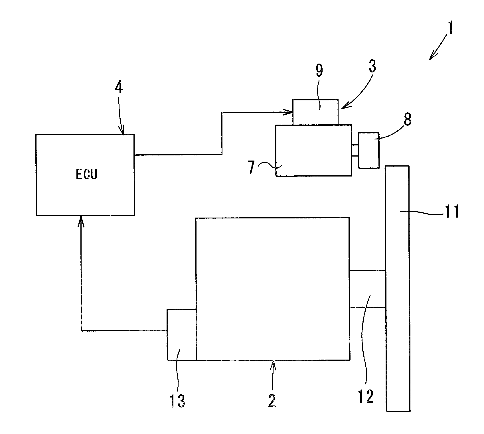
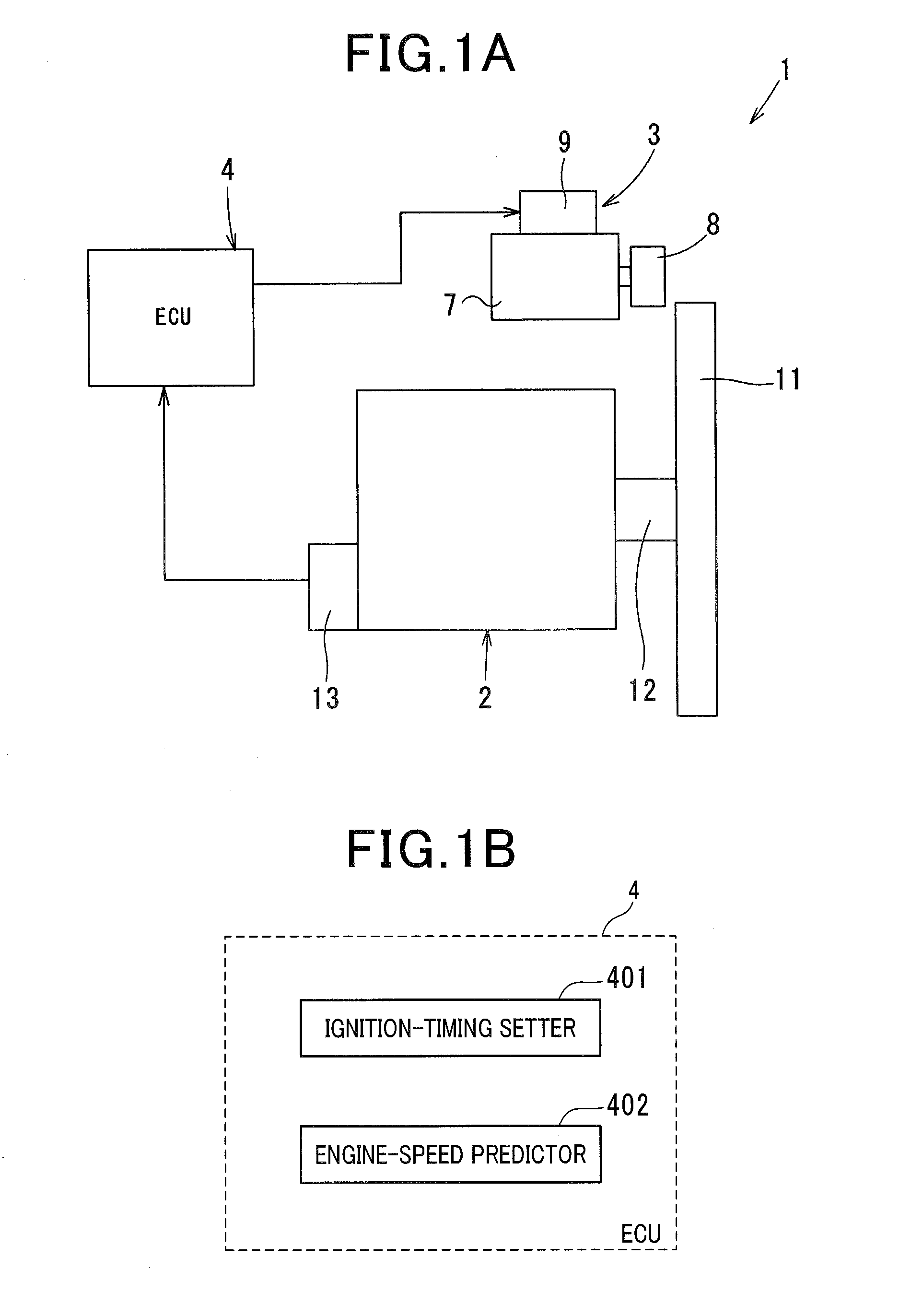
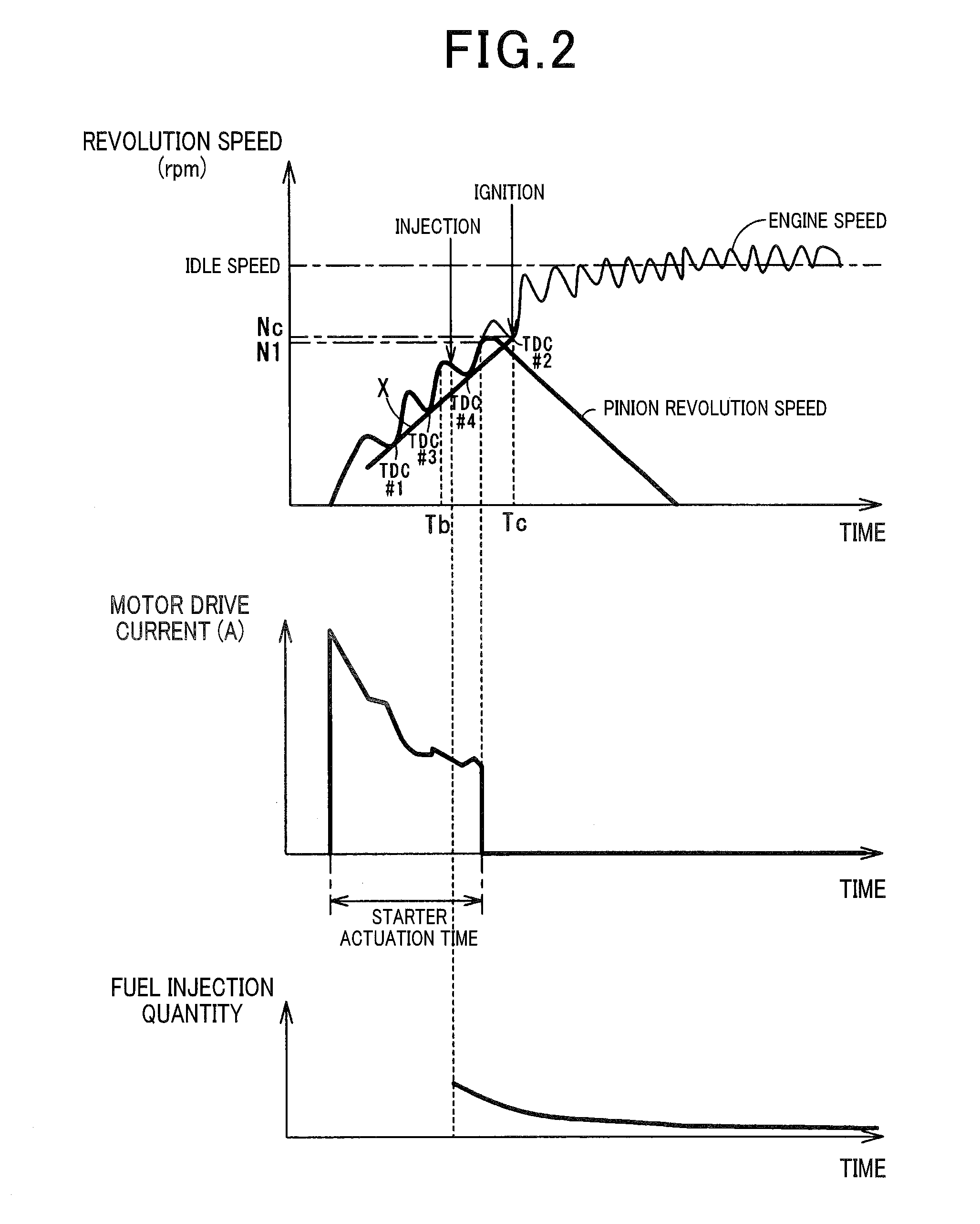
[0025]Referring now to the accompanying drawings wherein like reference numerals refer to similar or identical parts throughout the several views, and more specifically to FIGS. 1A, 1B, 2, and 3 thereof, there is shown an apparatus 1 for starting an engine 2. The engine 2 may be a multiple cylinder engine. The apparatus 1 is hereinafter also referred to as an engine starting apparatus.

[0026]As shown in FIG. 1A, the engine starting apparatus 1, applied to a vehicle equipped with an idle-stop system for automatically controlling stopping and restarting of the engine 2, includes a starter 3 for starting the engine 2, and an electronic control unit (ECU) 4 for controlling the operations of the starter 3 and an igniter (not shown).

[0027]The engine 2 of the present embodiment is a spark-ignited gasoline engine.

[0028]The starter 3 is an inertia-engagement-type starter capable of rotating up to speeds above an idle speed of the engine 2 and includes a motor 7, a pinion 8, an electromagnetic...


PUM


Abstract

An engine starting apparatus including a starter including a motor configured to generate a rotational force, and a pinion configured to transfer the rotational force of the motor to a ring gear. The starter is configured to crank an engine at a specific revolution-speed increase rate to increase a revolution speed of the engine to a predetermined revolution speed equal to or greater than 450 rpm. The apparatus further includes an ignition-timing setter configured to set an ignition timing at which fuel in a combustion chamber of the engine is ignited while the revolution speed of the engine is increased during cranking of the engine by the starter or during coasting of the engine after termination of cranking of the engine by the starter, and an engine-speed predictor configured to predict a revolution speed of the engine at the ignition timing based on the specific revolution-speed increase rate.

Description

CROSS-REFERENCE TO RELATED APPLICATION[0001]This application is based on and claims the benefit of priority from earlier Japanese Patent Applications No. 2014-75438 filed Apr. 1, 2014, the descriptions of which are incorporated herein by reference.BACKGROUND[0002]1. Technical Field[0003]The present invention relates to an engine starting apparatus.[0004]2. Related Art[0005]A conventional technique for starting an engine uses an inertia-engagement-type starter to crank the engine until a predetermined revolution speed of the engine NO within a low engine-speed range (5400 rpm) is reached, and after the revolution speed of the engine NO is reached, increases the revolution speed of the engine to an idle speed with combustion in a combustion chamber. Usually, as shown in FIG. 4, increasing the revolution speed of the engine to the idle speed requires multiple fuel injections and ignitions (multiple fuel injections in the case of the diesel engine). For example, first fuel injection and...

Claims


Application Information

Patent Timeline
IPC IPC(8): F02N11/08F02P9/00F02N15/04
CPCF02N11/08F02P9/00F02N15/04F02D2200/04F02D41/062F02N11/0848F02N11/0855F02N15/067F02P5/045F02P5/1506F02D2200/1012F02N2200/022F02N2200/102Y02T10/40
Inventor FUJITA, TATSUYAMURATA, MITSUHIRO
Owner DENSO CORP
Why Eureka
Eureka Blog
Learn More