Multiphase metering with ultrasonic tomography and vortex shedding

Active Publication Date: 2015-10-01
SAUDI ARABIAN OIL CO
View PDF3 Cites 19 Cited by
  • Summary
  • Abstract
  • Description
  • Claims
  • Application Information

AI Technical Summary

Benefits of technology

[0008]Briefly, the present invention provides a new and improved apparatus for sensing in situ measures of multiphase flow of a fluid in a conduit. The apparatus includes a bluff body in the conduit forming a vortex street in the fluid in the conduit, and an orifice plate in the conduit amplifying the vortex street and lowering the frequency of the vortex street formed by the bluff body. The apparatus also includes a sensor forming measures of the velocity of the fluid flow in the conduit downstream of the orifice plate. The apparatus also includes an array of a plurality of ultrasonic transceivers mounted about the periphery of the conduit transmitting and receiving energy for travel through the fluid in the conduit. The array of a plurality of ultrasonic transceivers mounted about the periphery of the conduit further receives energy after travel through the fluid in the conduit.
[0009]The present invention also provides a new and improved apparatus for forming in situ measures of multiphase flow of a fluid in a conduit. The apparatus includes a bluff body in the conduit forming a vortex street in the fluid in the conduit, and an orifice plate in the conduit amplifying the vortex street and lowering the frequency of the vortex street formed by the bluff body. The apparatus also includes a sensor sensing measures of the fluid flow in the conduit downstream of the orifice plate, along with an array of a plurality of ultrasonic transceivers mounted about the periphery of the conduit transmitting and receiving energy for travel through the fluid in the conduit. The array of a plurality of ultrasonic transceivers mounted about the periphery of the conduit further receives energy after travel through the fluid in the conduit. The apparatus also includes a data processing system forming measures of multiphase flow of the fluid in the. The data processing system forms measures of the fluid flow velocity based on the sensed measures of the fluid flow in the conduit, and also forms tomographic images of the multiphase flow in the conduit based on ultrasonic energy travel through the fluid in the conduit from transmitting transceivers of the array of a plurality of transceivers to receiving transceivers of the array.
[0010]The present invention also includes a new and improved apparatus for sensing in situ measures of multiphase flow of a fluid in a conduit. The apparatus includes an array of a plurality of ultrasonic transceivers mounted about the periphery of the conduit transmitting and receiving energy for travel through the fluid in the conduit. The array of a plurality of ultrasonic transceivers mounted about the periphery of the conduit further receives energy after travel through the fluid in the conduit. The array of a plurality of transceivers is mounted in an inclined plane relative to a plane perpendicular to a longitudinal axis of the flow conduit.
[0011]The present invention also includes a new and improved apparatus for sensing in situ measures of multiphase flow of a fluid in a conduit. The apparatus includes a bluff body in the conduit forming a vortex street in the fluid in the conduit, and an orifice plate in the conduit amplifying the vortex street and lowering the frequency of the vortex street formed by the bluff body. The apparatus also includes a sensor forming measures of the velocity of the fluid flow in the conduit downstream of the orifice plate, and an array of a plurality of ultrasonic transceivers mounted about the periphery of the conduit transmitting and receiving energy for travel through the fluid in the conduit. The array of a plurality of ultrasonic transceivers mounted about the periphery of the conduit further receiving energy aft

Problems solved by technology

Because of the different fluid properties of water (brine), oil and g

Method used


Image

  • Multiphase metering with ultrasonic tomography and vortex shedding
  • Multiphase metering with ultrasonic tomography and vortex shedding
  • Multiphase metering with ultrasonic tomography and vortex shedding

Examples


Example

Combined Ultrasound Tomography and Vortex Shedding Systems Basic Tomography System

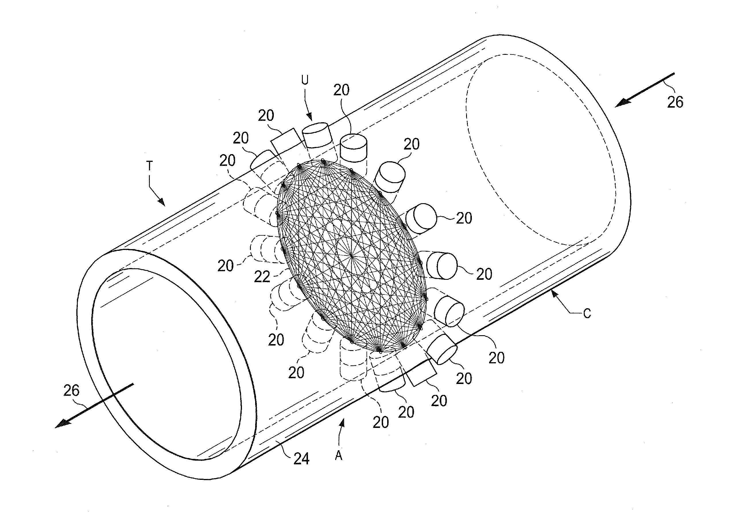
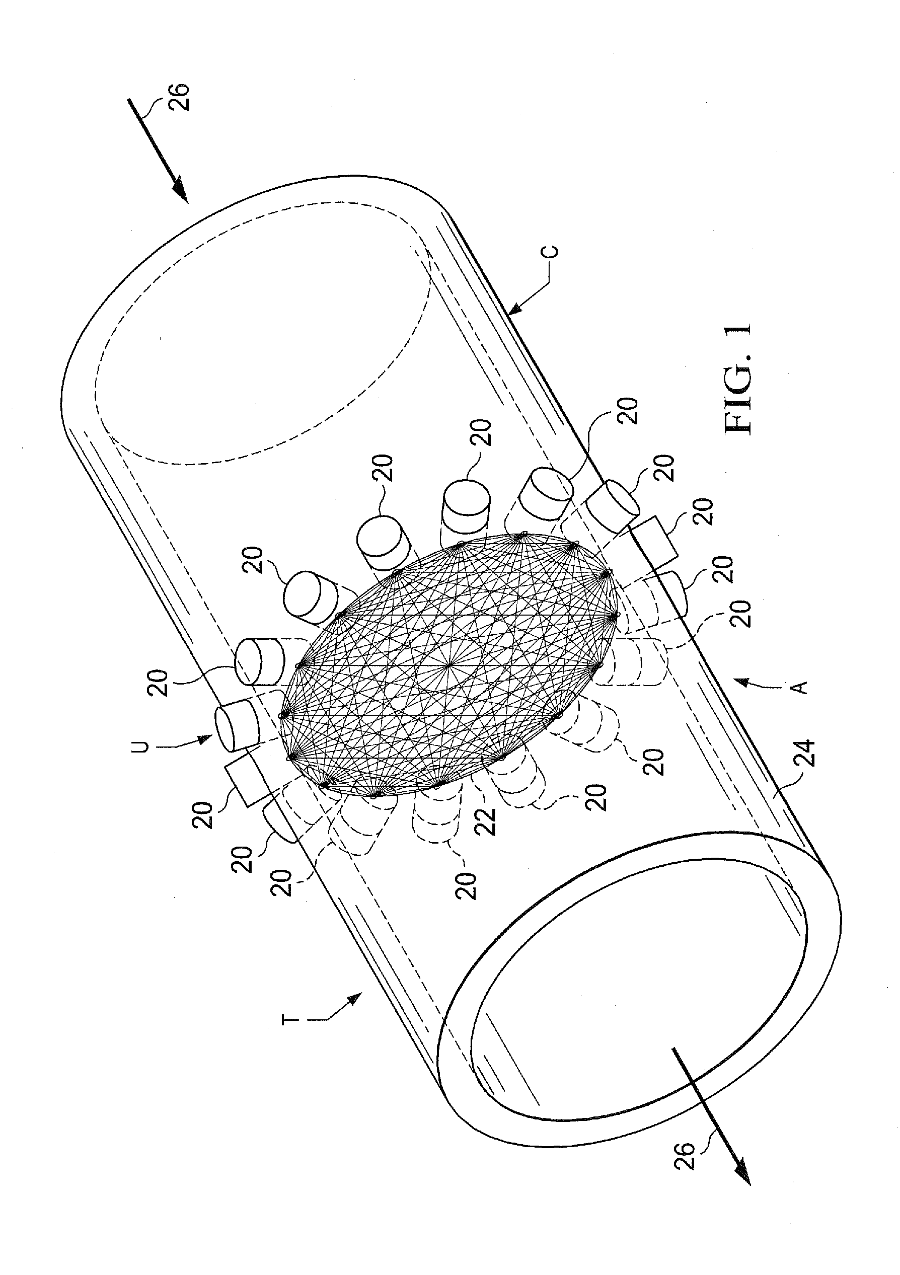
[0029]By way of background, an introductory explanation of certain commonly owned U.S. Patent Applications of which applicants are named as inventor or co-inventors is provided. FIG. 1 shows the basic configuration of a tomography system T which can be used to measure the cross sectional composition of oil, water and gas in a multiphase flow. This tomography system T is the subject of commonly owned co-pending U.S. patent application Ser. No. 14 / 595,683 filed Jan. 13, 2015 and having an effective filing date of Apr. 1, 2014. This co-pending application names each of the inventors of the present application as co-inventors. The subject matter of this co-pending application is incorporated herein by reference for all purposes.

[0030]The tomographic system T is utilized to form tomographic images of multiphase flow in a flow conduit C, for example in production tubing or surface piping as shown at 24. The ...


PUM


Abstract

Ultrasound tomography arrays and vortex shedding devices are provided which measure average flow velocity through Doppler shift of the fluid as well as cross sectional multiphase fluid composition in pipe or tubing conduits. Multiple tomographic arrays in conjunction with correlation of sensed flow patterns in time provided determination of flow velocity as well as cross sectional multiphase fluid composition. The tomographic arrays may be arranged in a skewed or slanted plane to measure velocity fluctuations downstream of a vortex shedding device where the period and amplitude of the fluctuations is correlated with the mass flow of the fluid. Additionally, the tomographic arrays provide the relative composition of the multiphase fluid. The multiple arrays together with correlation to determine velocity fluctuations downstream of a vortex shedding device where the period and amplitude of the fluctuations is correlated with the mass flow of the fluid. Additionally the tomographic arrays output the relative composition of the multiphase fluid.

Description

CROSS-REFERENCE TO RELATED APPLICATIONS[0001]This application claims priority from U.S. Provisional Application No. 61 / 973,367, filed Apr. 1, 2014, and its related co-pending, commonly owned U.S. patent application Ser. No. 14 / 595,689, filed Jan. 13, 2015. For purposes of United States patent practice, this application incorporates the contents of the Provisional Application by reference in entirety.[0002]Filed of even date herewith are related commonly owned U.S. Patent Application entitled FLOW LINE MOUNTING ARRANGEMENT FOR FLOW SYSTEM TRANSDUCERS, (Attorney Docket No. 004159.005374), and U.S. Patent Application entitled FLOW DATA ACQUISITION AND TELEMETRY PROCESSING SYSTEM, (Attorney Docket No. 004159.005375), each having the same co-inventors as the present application.BACKGROUND OF THE INVENTION[0003]1. Field of the Invention[0004]The present invention relates to metering of multiphase flow in conduits, and more particularly to multiphase metering with ultrasonic tomography and...

Claims


Application Information

Patent Timeline
IPC IPC(8): G01F1/66G01F1/74G01F1/32
CPCG01F1/66G01F1/74G01F1/3209G01N29/036G01N2291/017G01N2291/0222G01N2291/0224G01N2291/106G01F1/3218
Inventor BLACK, MICHAEL JOHNNOUI-MEHIDI, MOHAMED NABILAHMAD, TALHA JAMAL
Owner SAUDI ARABIAN OIL CO
Why Eureka
Try Eureka