Virtual image display device and head-mounted display

Active Publication Date: 2015-10-01
SEIKO EPSON CORP
View PDF3 Cites 68 Cited by
  • Summary
  • Abstract
  • Description
  • Claims
  • Application Information

AI Technical Summary

Benefits of technology

[0007]An advantage of the invention is to provide a virtual image display device having a simple structure and capable of magnifying the picture light beam, and a head-mounted display, which is equipped with such a virtual image display device, and is easy for the observer to visually recognize.
[0008]Such an advantage can be achieved by the following configurations.
[0009]A virtual image display device according to an aspect of the invention includes an image generation section adapted to generate a picture light beam modulated based on a video signal, and an optical element including a plane of incidence to which the picture light beam emitted from the image generation section is input, and an exit surface adapted to emit a picture light beam obtained by enlarging a cross-sectional area of the picture light beam input to the plane of incidence, the optical element includes a first light guide section and a second light guide section adapted to connect the plane of incidence and the exit surface to each other to guide the picture light beam emitted from the image generation section, and a

Problems solved by technology

However, such a head-mounted display requires a detection device of the pupil position, constituents (e.g., eyepiece lenses, and a position changing device and a control section of an image light emission unit

Method used


Image

  • Virtual image display device and head-mounted display
  • Virtual image display device and head-mounted display
  • Virtual image display device and head-mounted display

Examples


first embodiment

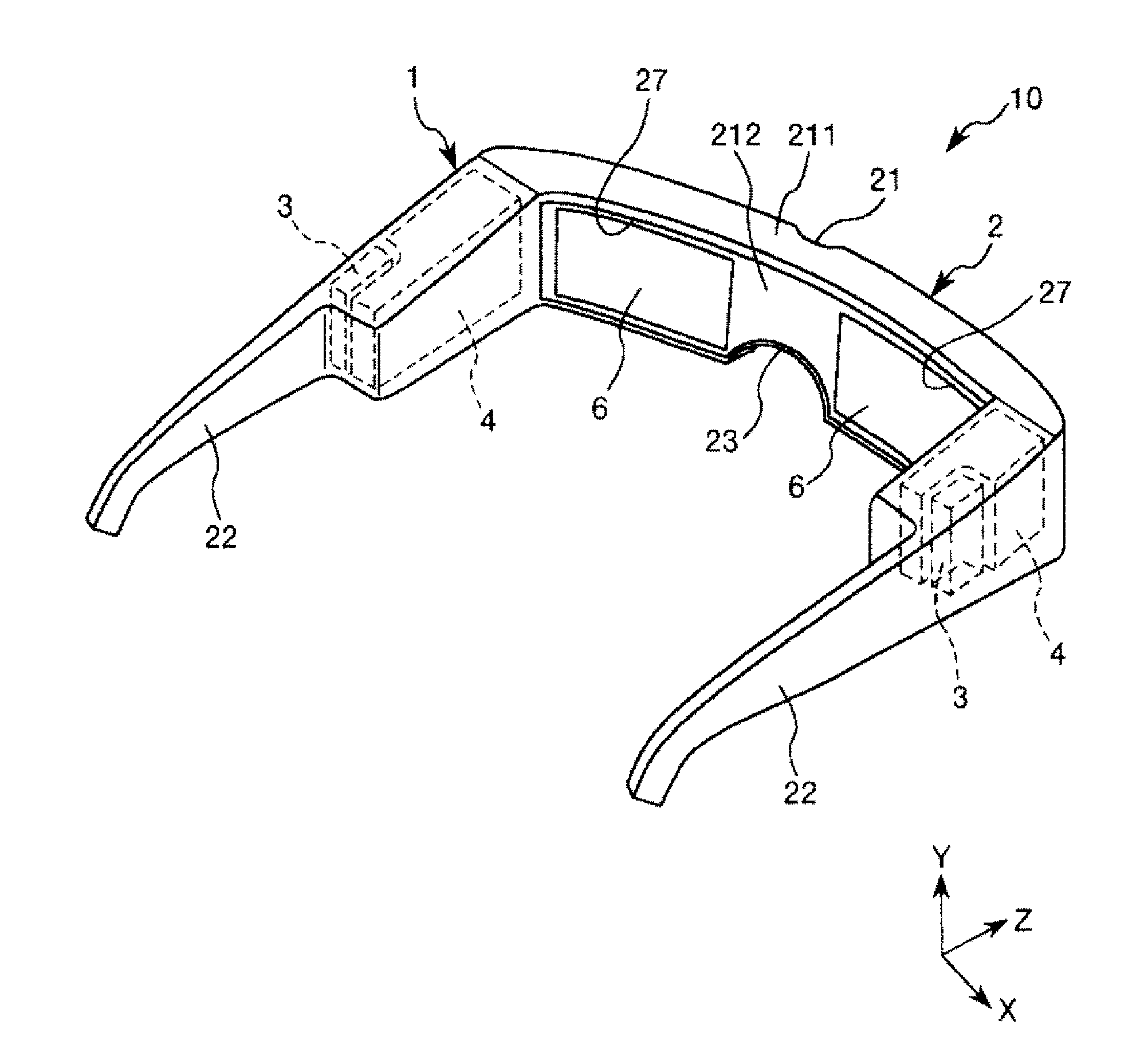
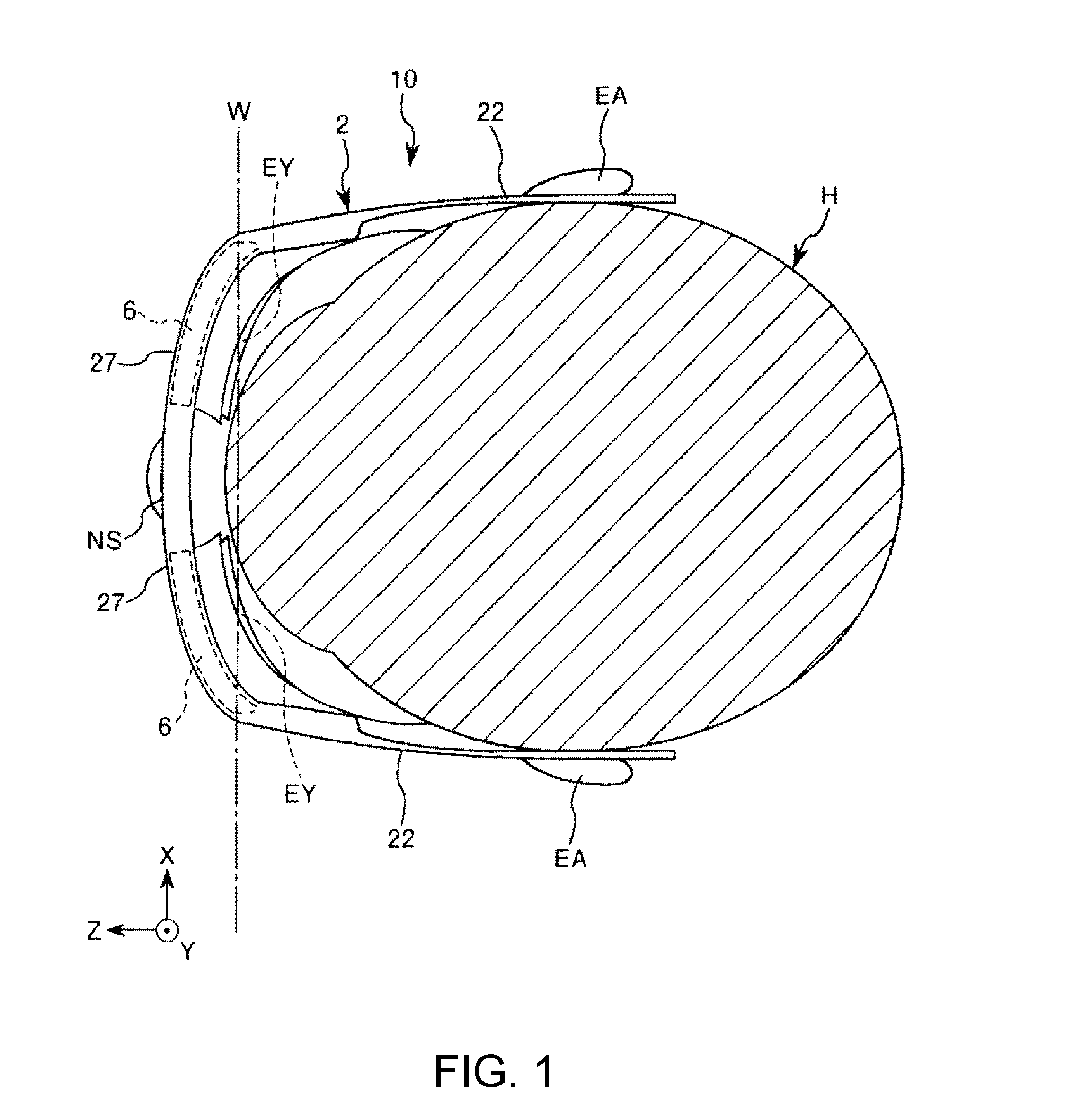
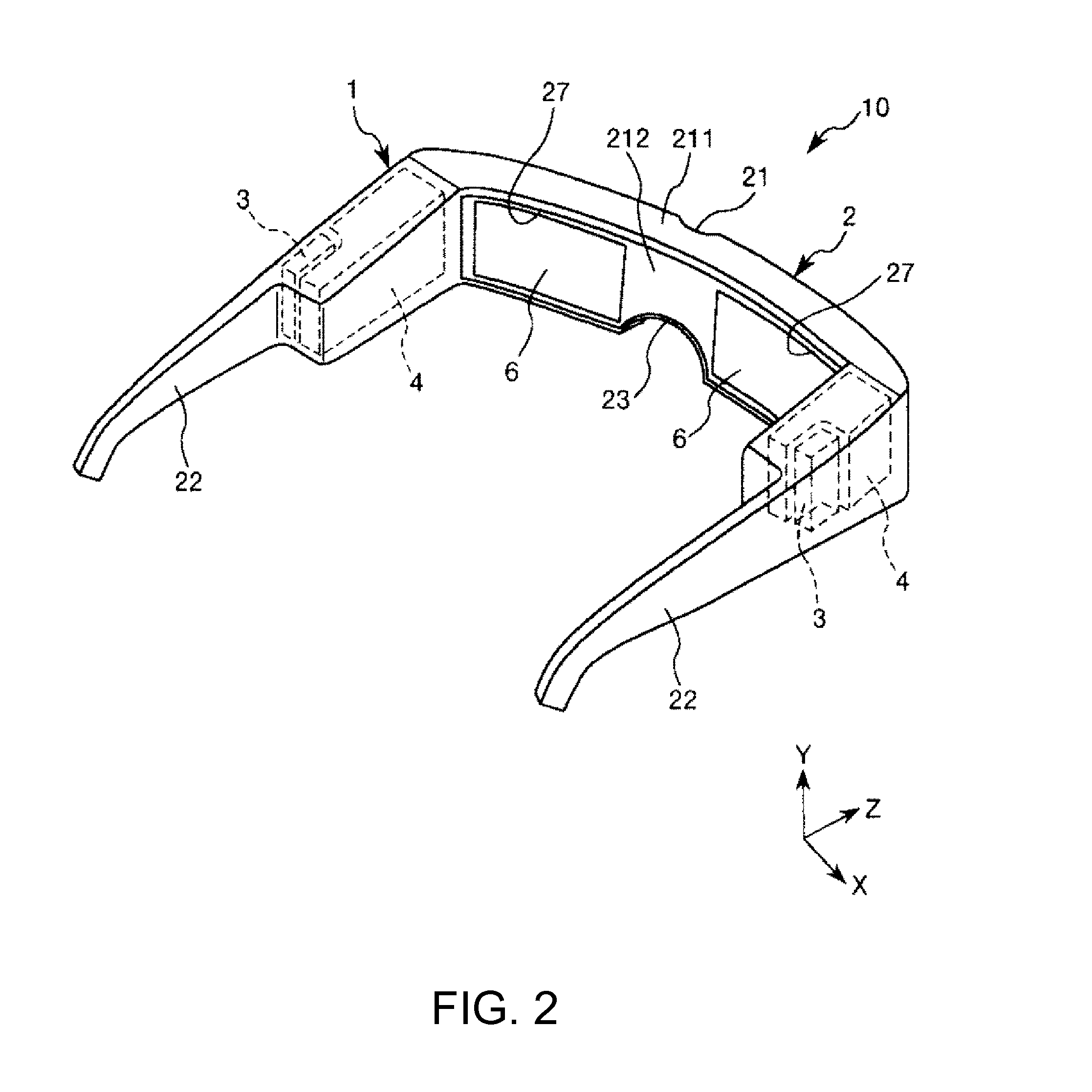
[0060]FIG. 1 is a diagram showing a schematic configuration of a head-mounted display equipped with a virtual image display device according to a first embodiment, FIG. 2 is a schematic perspective view of the head-mounted display shown in FIG. 1, FIG. 3 is a diagram schematically showing a configuration of the virtual image display device shown in FIG. 1, FIG. 4 is a diagram schematically showing a configuration of an image generation section shown in FIG. 2, FIGS. 5A and 5B are diagrams each showing an example of a drive signal of a drive signal generation section shown in FIG. 4, FIG. 6 is a plan view of a light scanning section shown in FIG. 4, FIG. 7 is a cross-sectional view (a cross-sectional view along an X1 axis) of the light scanning section shown in FIG. 6, FIGS. 8A through 8D are diagrams showing a schematic configuration of an optical element shown in FIG. 3, wherein FIG. 8A is a front view, FIG. 8B is a plan view, FIG. 8C is a right side view, and FIG. 8D is a left sid...

second embodiment

[0239]Next, a virtual image display device according to a second embodiment of the invention will be explained.

[0240]FIGS. 11A through 11D are diagrams showing a schematic configuration of an optical element provided to the virtual image display device according to the second embodiment, wherein FIG. 11A is a front view, FIG. 11B is a plan view, FIG. 11C is a right side view, and FIG. 11D is a left side view. FIG. 12 is a diagram for explaining paths of the picture light beam having entered an optical element shown in FIGS. 11A through 11D.

[0241]Hereinafter, the virtual image display device according to the second embodiment of the invention will be described with reference to these drawings with a focus mainly on the differences from the embodiment described above, and the explanation regarding similar matters will be omitted.

[0242]The second embodiment is substantially the same as the embodiment described above except the point that the configuration of the magnifying optical sect...

third embodiment

[0254]Next, a virtual image display device according to a third embodiment of the invention will be explained.

[0255]FIGS. 13A through 13D are diagrams showing a schematic configuration of an optical element provided to the virtual image display device according to the third embodiment, wherein FIG. 13A is a front view, FIG. 13B is a plan view, FIG. 13C is a right side view, and FIG. 13D is a left side view. FIG. 14 is a diagram for explaining paths of the picture light beam having entered the optical element shown in FIGS. 13A through 13D.

[0256]Hereinafter, the virtual image display device according to the third embodiment of the invention will be described with reference to these drawings with a focus mainly on the differences from the embodiment described above, and the explanation regarding similar matters will be omitted.

[0257]The third embodiment is substantially the same as the embodiment described above except the point that the configuration of the optical element is differe...


PUM


Abstract

A virtual image display device includes: an image generator generating a picture light beam modulated based on a video signal; and an optical element including a plane of incidence to which the picture light beam emitted from the image generator is input, and an exit surface emitting the picture light beam after a cross-sectional area of the picture light beam input to the plane of incidence has been enlarged. The optical element includes a first light guide and a second light guide connecting the plane of incidence and the exit surface and guiding the picture light beam. A first light branching layer is disposed between the first and second light guides, and partially reflects and partially transmits the picture light beam. The picture light beam emitted from the image generator obliquely enters the first light branching layer.

Description

BACKGROUND[0001]1. Technical Field[0002]The present invention relates to a virtual image display device and a head-mounted display.[0003]2. Related Art[0004]In recent years, as a virtual image display device for making the formation and observation of a virtual image possible such as a head-mounted display (HMD), there have been proposed various devices that guide a picture light beam from a display element to the pupils of the observer using a light guide plate.[0005]As such a virtual display device, there has been known a head-mounted display as described in JP-A-2011-75956.[0006]The head-mounted display described in JP-A-2011-75956 has a configuration of moving the picture light beam entering the pupils in accordance with the movement of the human eyes to thereby realize a head-mounted display that is easy for user to visually recognize. However, such a head-mounted display requires a detection device of the pupil position, constituents (e.g., eyepiece lenses, and a position chan...

Claims


Application Information

Patent Timeline
IPC IPC(8): G06T19/00G02B27/01F21V8/00
CPCG06T19/006G02B6/0076G02B2027/0178G02B27/0172G02B6/0031G02B2027/0174G02B2027/0116G02B6/00G02B27/01
Inventor YONEKUBO, MASATOSHI
Owner SEIKO EPSON CORP
Why Eureka
Try Eureka