Capacitive programmable gain amplifier

a programmable gain amplifier and capacitive technology, applied in the direction of amplifiers using switched capacitors, analog signal digital control, gain control, etc., can solve the problems of reducing linearity and reducing input voltage range, reducing linearity and input voltage range, and inactive capacitors increasing the noise of capacitive pga

Active Publication Date: 2015-10-01
QUALCOMM INC
View PDF1 Cites 14 Cited by
  • Summary
  • Abstract
  • Description
  • Claims
  • Application Information

AI Technical Summary

Benefits of technology

[0003]Wireless telephones may include microphones configured to capture audio signals. A capacitive programmable gain amplifier (PGA) may be used to amplify a signal, such as a microphone signal (e.g., an audio signal). The capacitive PGA may include multiple input capacitors coupled to a common mode input of an operational amplifier (e.g., virtual ground) and multiple feedback capacitors coupled to an output of the operational amplifier and to virtual ground. Each input capacitor may be selectively coupled to or decoupled from the common mode input using corresponding switching circuitry to control the gain of the capacitive PGA. In a similar manner, each feedback capacitor may be selectively coupled to or decoupled from the common mode input using corresponding switching circuitry to control the gain of the capacitive PGA. However, leakage current from the switching circuitry may flow to the common mode input (e.g., a high impedance node) which may reduce linearity and reduce an input voltage range. For example, the leakage current may reduce headroom of the capacitive PGA that is used for voltage swings at the output of the operational amplifier. The reduced headroom may cause reduced linearity and input voltage range. In addition, decoupling input capacitors and feedback capacitors may reduce noise performance. For example, inactive capacitors may increase an amount of noise of the capacitive PGA.

Problems solved by technology

However, leakage current from the switching circuitry may flow to the common mode input (e.g., a high impedance node) which may reduce linearity and reduce an input voltage range.
The reduced headroom may cause reduced linearity and input voltage range.
For example, inactive capacitors may increase an amount of noise of the capacitive PGA.

Method used


Image

  • Capacitive programmable gain amplifier
  • Capacitive programmable gain amplifier
  • Capacitive programmable gain amplifier

Examples


Embodiment Construction

[0010]The detailed description set forth below is intended as a description of exemplary designs of the present disclosure and is not intended to represent the only designs in which the present disclosure can be practiced. The term “exemplary” is used herein to mean “serving as an example, instance, or illustration.” Any design described herein as “exemplary” is not necessarily to be construed as preferred or advantageous over other designs. The detailed description includes specific details for the purpose of providing a thorough understanding of the exemplary designs of the present disclosure. It will be apparent to those skilled in the art that the exemplary designs described herein may be practiced without these specific details. In some instances, well-known structures and devices are shown in block diagram form in order to avoid obscuring the novelty of the exemplary designs presented herein.

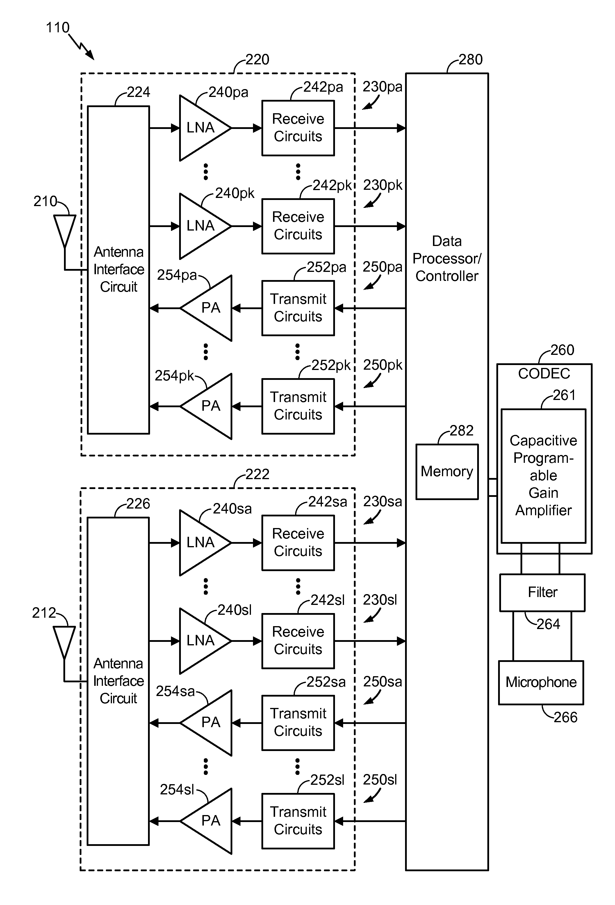
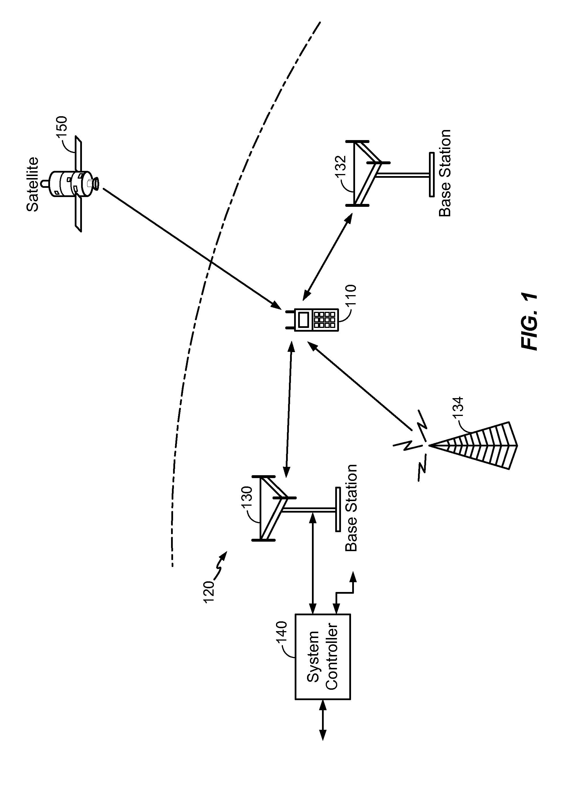
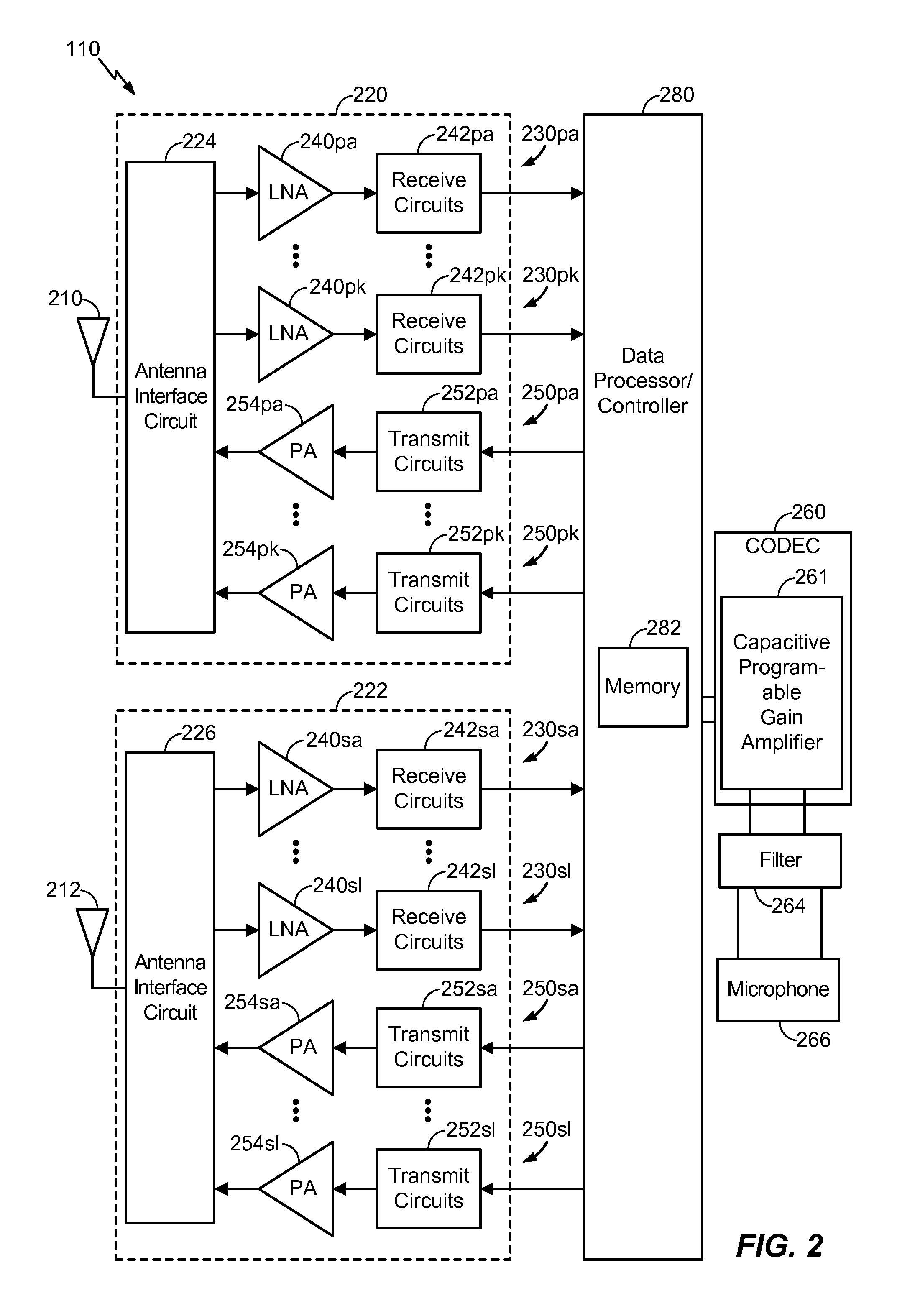
[0011]FIG. 1 shows a wireless device 110 communicating with a wireless communication s...


PUM


Abstract

An apparatus includes an operational amplifier and a plurality of capacitors coupled to an input terminal of the operational amplifier and configured to be selectively coupled to receive one of an input voltage signal and an output voltage signal of the operational amplifier.

Description

I. FIELD[0001]The present disclosure is generally related to a capacitive programmable gain amplifier.II. DESCRIPTION OF RELATED ART[0002]Advances in technology have resulted in smaller and more powerful computing devices. For example, there currently exist a variety of portable personal computing devices, including wireless computing devices, such as portable wireless telephones, personal digital assistants (PDAs), and paging devices that are small, lightweight, and easily carried by users. More specifically, portable wireless telephones, such as cellular telephones and Internet protocol (IP) telephones, can communicate voice and data packets over wireless networks. Further, many such wireless telephones include other types of devices that are incorporated therein. For example, a wireless telephone can also include a digital still camera, a digital video camera, a digital recorder, and an audio file player. Also, such wireless telephones can process executable instructions, includi...

Claims


Application Information

Patent Timeline
Patent Type & Authority Applications(United States)
IPC IPC(8): H03G3/00H03F3/45H03F3/00
CPCH03G3/008H03F3/005H03F3/45071H03F2203/45118H03F2200/267H03F2203/45156H03F2200/129H03F3/45475H03G1/0088H03G3/001H03F2203/45514
Inventor HUANG, WENCHANGSHAH, PETER JIVANAZIN, MEYSAMMEHRABI, ARASH
Owner QUALCOMM INC
Why Eureka
Try Eureka