Range switching device

a switching device and range technology, applied in the direction of differential gearings, mechanical devices, gearings, etc., can solve the problems of difficult attachment, stricter restrictions on the layout around the transmission, and high complexity of the layout of the wiring member and the respective components inside the housing, so as to facilitate the attachment around the transmission and suppress the increase in the complexity of the layout

Active Publication Date: 2015-10-08
MITSUBISHI ELECTRIC CORP
View PDF8 Cites 15 Cited by
  • Summary
  • Abstract
  • Description
  • Claims
  • Application Information

AI Technical Summary

Benefits of technology

[0010]The invention was devised to solve the problems discussed above and has an object to provide a range switching device not only capable of suppressing an i

Problems solved by technology

This configuration, however, raises a problem that not only an extremely long wiring member to connect the motor and the encoder all the way to the connector is required, but also a layout of the wiring member and respective components inside the housing becomes highly complex.
This configuration raises another problem that restrictions impo

Method used


Image

  • Range switching device
  • Range switching device
  • Range switching device

Examples


first embodiment

[0022]Hereinafter, the invention will be described with reference to FIG. 1 through FIG. 6 showing a first embodiment.

[0023]Same reference numerals denote same or equivalent portions in the respective drawings.

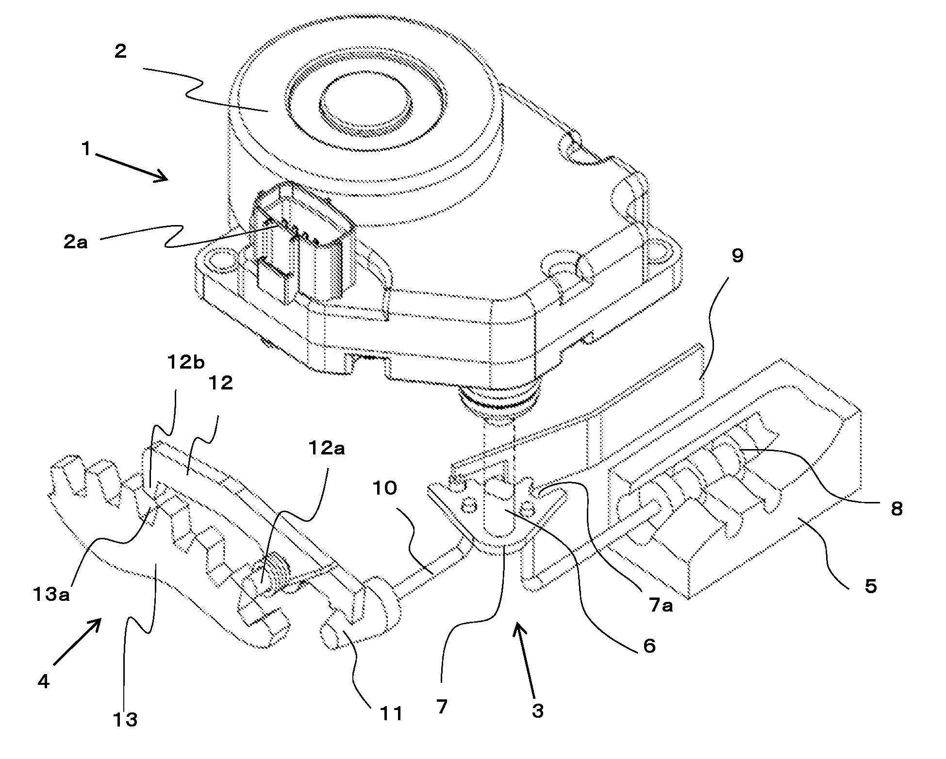
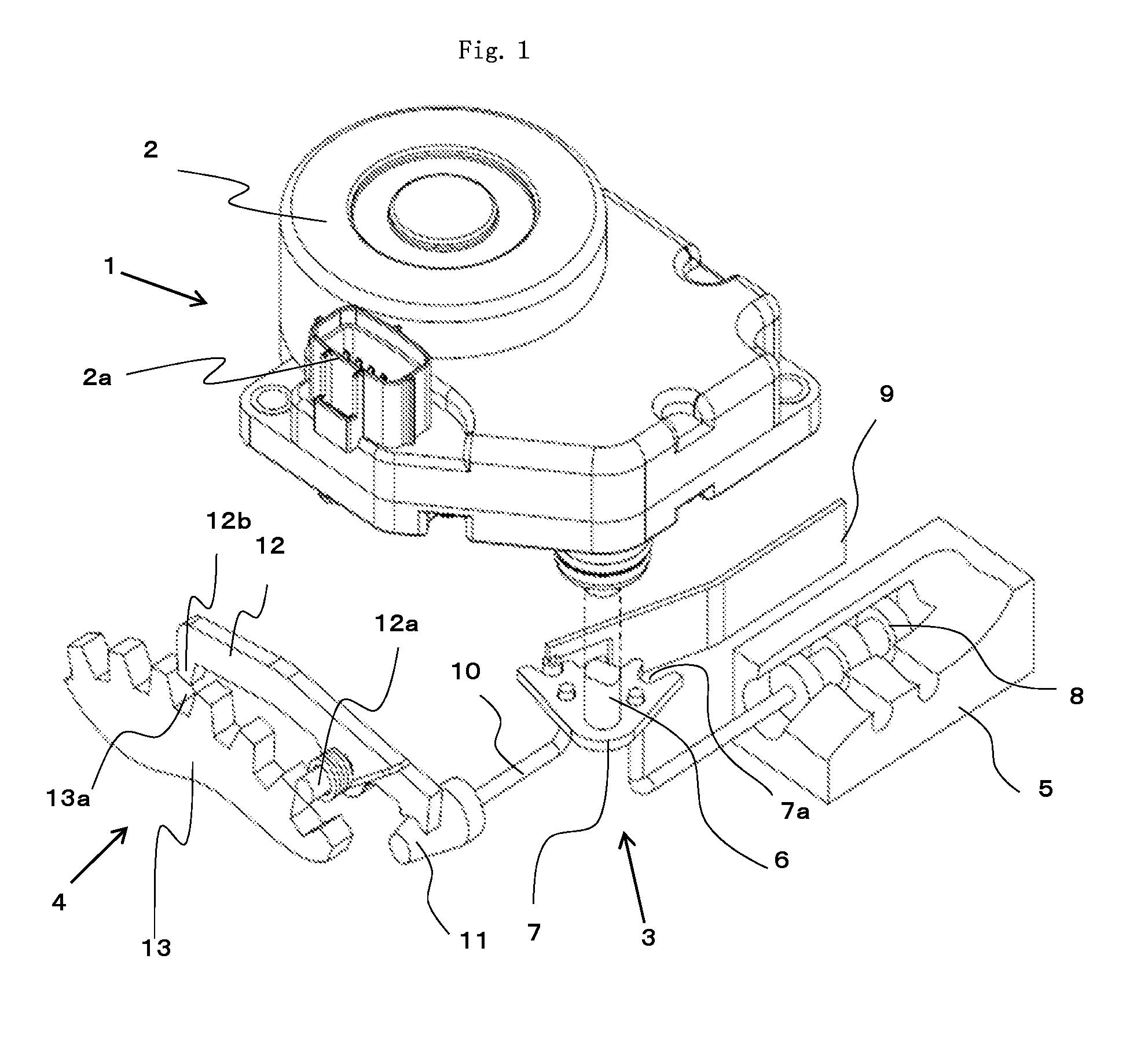
[0024]FIG. 1 schematically shows a range switching mechanism 1 to which a range switching device according to the first embodiment of the invention is applied. The range switching mechanism 1 is formed of a range switching device 2 which is a major portion of the invention, a detent mechanism 3, a parking mechanism 4, and a valve body 5.

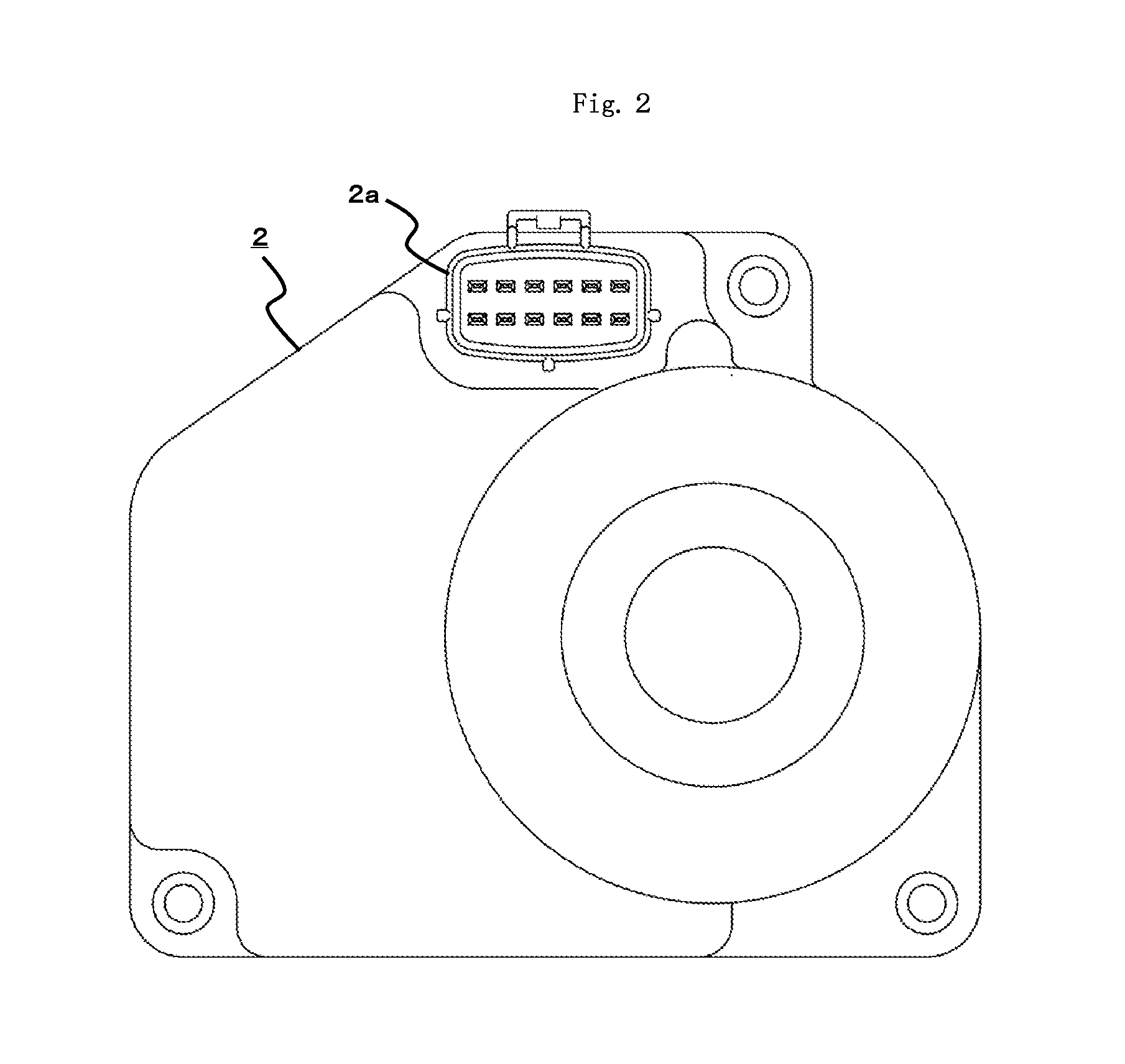
[0025]The range switching device 2 is formed so as to be attached to an automatic transmission mounted, for example, on a vehicle, and includes a connector 2a to which is supplied a shift signal (electrical signal) from a shift lever (range selection portion) selected by a driver. According to this shift signal, the range switching device 2 rotationally drives a shift shaft 6, which is a drive target linked to its own output shaft, and thereby ...


PUM


Abstract

A range switching device includes: a range switching portion having an output shaft rotatably supported inside a housing and switchable to ranges corresponding to output shaft turning positions; a motor attached with its motor shaft spaced apart from a shaft center of the output shaft; a reducer mechanism linked to the motor and the range switching portion; and a control board controlling rotation of the motor. The reducer mechanism has a planetary gear reducer mechanism formed of a sun gear, planetary gears, an internal gear, and a carrier supporting the planetary gears, and a spur gear reducer mechanism formed of a pinion and a main gear linked to the pinion. The control board is installed oppositely to the output shaft and the motor.

Description

BACKGROUND OF THE INVENTION[0001]1. Field of the Invention[0002]The present invention relates to a range switching device including so-called a shift-by-wire system that sets a shift range selected by a driver using, for example, a shift lever, via an electrical signal.[0003]2. Description of the Background Art[0004]There is a range switching device including a motor, a cycloidal reducer portion, a parallel-shaft gear reducer portion, and an output shaft inside an outer-frame member as disclosed, for example, in Patent Literature 1.[0005]The range switching device disclosed in Patent Literature 1 is configured as follows. That is, an electronic control unit is installed on the outside of the outer-frame member and a housing main body of the range switching device is provided with a connector protruding radially outward. The range switching device and the electronic control unit are electrically connected to each other by coupling a connector storing wirings from the electronic contr...

Claims


Application Information

Patent Timeline
IPC IPC(8): F16H61/32F16H61/00
CPCF16H61/32F16H2061/326F16H2061/2892F16H61/0006
Inventor NAGAHORI, TATSUROURYU, TAKUYAKURITA, KAZUHISASUGANO, CHIAKIKAWASAKI, NARUHIKO
Owner MITSUBISHI ELECTRIC CORP
Why Eureka
Try Eureka