Wide angle lens and imaging apparatus
a wide angle lens and imaging apparatus technology, applied in the field of wide angle lenses and imaging apparatuses, can solve the problems of reducing the yield rate during molding and assembly, the refractive power of each lens becoming too strong, and the deterioration of molding characteristics, so as to achieve excellent optical performance, reduce manufacturing costs, and reduce the effect of manufacturing costs
- Summary
- Abstract
- Description
- Claims
- Application Information
AI Technical Summary
Benefits of technology
Problems solved by technology
Method used
Image

Examples
example 1
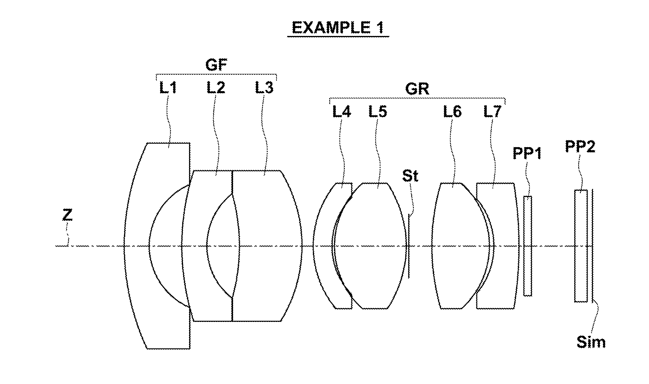
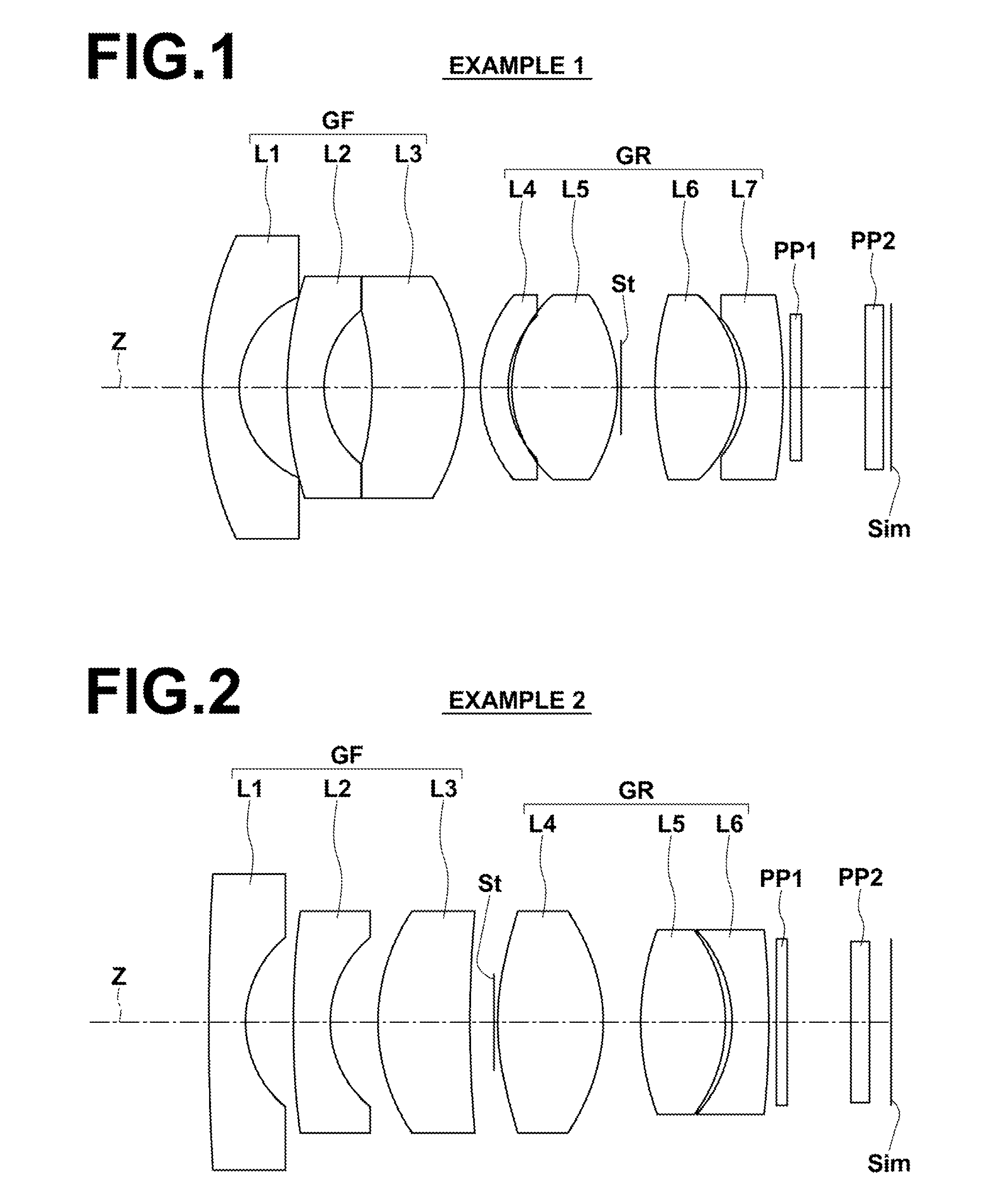
[0064]FIG. 1 is a diagram illustrating the lens configuration of a wide angle lens in Example 1. Since its illustration method has been described already, repletion of the explanation is omitted here.
[0065]As the schematic configuration of a wide angle lens in Example 1, the wide angle lens consists essentially of front group GF and rear group GR in this order from the object side. Front group GF consists of lens L1 having negative meniscus shape with its convex surface facing the object side, lens L2 having negative meniscus shape with its convex surface facing the object side and lens L3 having positive meniscus shape with its convex surface facing the image side in this order from the object side. Rear group GR consists of lens L4 having negative meniscus shape with its convex surface facing the object side, lens L5 having biconvex shape, aperture stop St, lens L6 having biconvex shape, and lens L7 having negative meniscus shape with its concave surface facing the object side in ...
example 2
[0081]FIG. 2 is a diagram illustrating the lens configuration of a wide angle lens in Example 2. The schematic configuration of the wide angle lens in Example 2 is substantially similar to the configuration of the wide angle lens in Example 1. Example 2 differs from Example 1 in that the entire system consists of six lenses, and that lens L3 has a positive meniscus shape with its convex surface facing the object side, and that rear group GR consists of lens L4 having a biconvex shape, lens L5 having a biconvex shape and lens L6 having a negative meniscus shape with its concave surface facing the object side in this order from the object side, and that aperture stop St is arranged between front group GF and rear group GR, and that aspheric lenses are lenses L2 and L4, and that four lenses of lenses L1 through L4 are made of an identical material of plastic, and that lenses L5 and L6 are made of glass.
[0082]Table 3 and Table 4 show basic lens data and aspherical coefficients of Exampl...
example 3
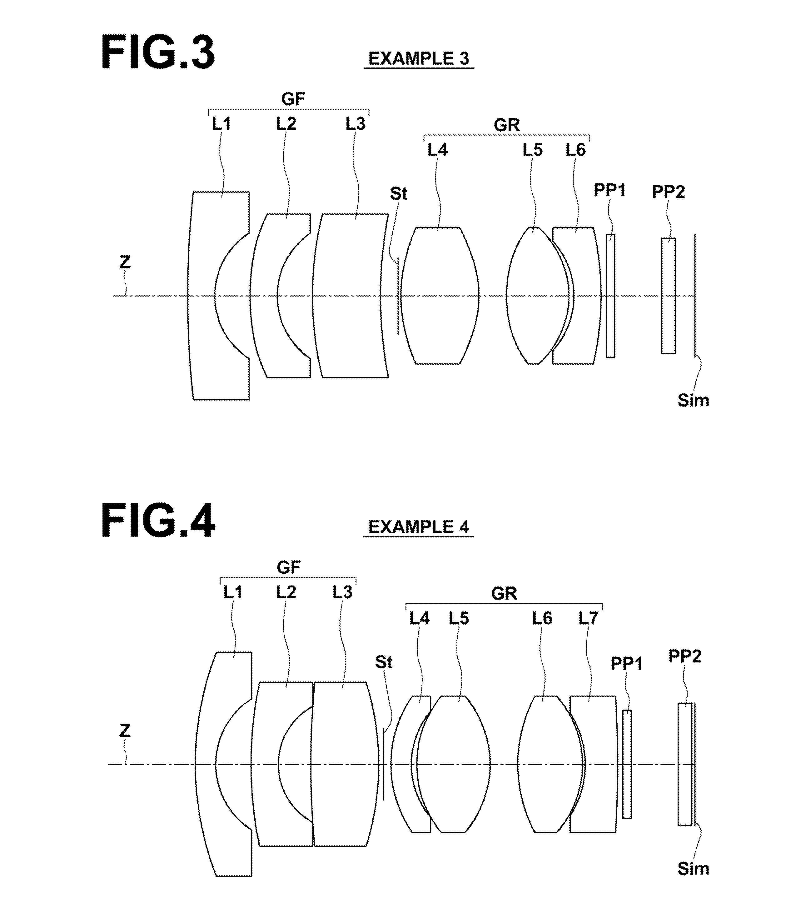
[0083]FIG. 3 is a diagram illustrating the lens configuration of a wide angle lens in Example 3. The schematic configuration of the wide angle lens in Example 3 is substantially similar to the configuration of the wide angle lens in Example 2. Example 3 differs from Example 2 in that aspheric lenses are lenses L1, L2, L4 and L5, and that five lenses of lenses L1 through L5 are made of an identical material of plastic, and that lens L6 is made of glass. Table 5 and Table 6 show basic lens data and aspherical coefficients of Example 3, respectively. FIG. 9, Sections A through C illustrate aberration diagrams of a spherical aberration, curvature of field, and distortion of the wide angle lens in Example 3, respectively, when the wide angle lens is focused on an object at infinity.
TABLE 5f = 2.363, Bf = 3.178, FNo. = 2.100, 2ω = 113.828°SiRiDiNdiνdj 133.95181.0001.5345055.7 2*2.73291.3001.00000 3*8.93811.0001.5345055.7 4*2.80691.3001.00000 512.54402.5001.5345055.7 615.51760.6501.00000 7...
PUM
| Property | Measurement | Unit |
|---|---|---|
| Angle | aaaaa | aaaaa |
Abstract
Description
Claims
Application Information
 - R&D
- Intellectual Property
- Life Sciences
- Materials
- Tech Scout
- Unparalleled Data Quality
- Higher Quality Content
- 60% Fewer Hallucinations
Browse by: Latest US Patents, China's latest patents, Technical Efficacy Thesaurus, Application Domain, Technology Topic, Popular Technical Reports.
© 2025 PatSnap. All rights reserved.Legal|Privacy policy|Modern Slavery Act Transparency Statement|Sitemap|About US| Contact US: help@patsnap.com