Upper Provided With Sponge Member in Heel Part
a technology of sponge member and upper, which is applied in the direction of upper, bootlegs, stiffners, etc., can solve the problems of insatiable conformity of the upper to the foot (the fitting property)
- Summary
- Abstract
- Description
- Claims
- Application Information
AI Technical Summary
Benefits of technology
Problems solved by technology
Method used
Image
Examples
embodiment 1
FIGS. 4 to 5D Show Embodiment 1
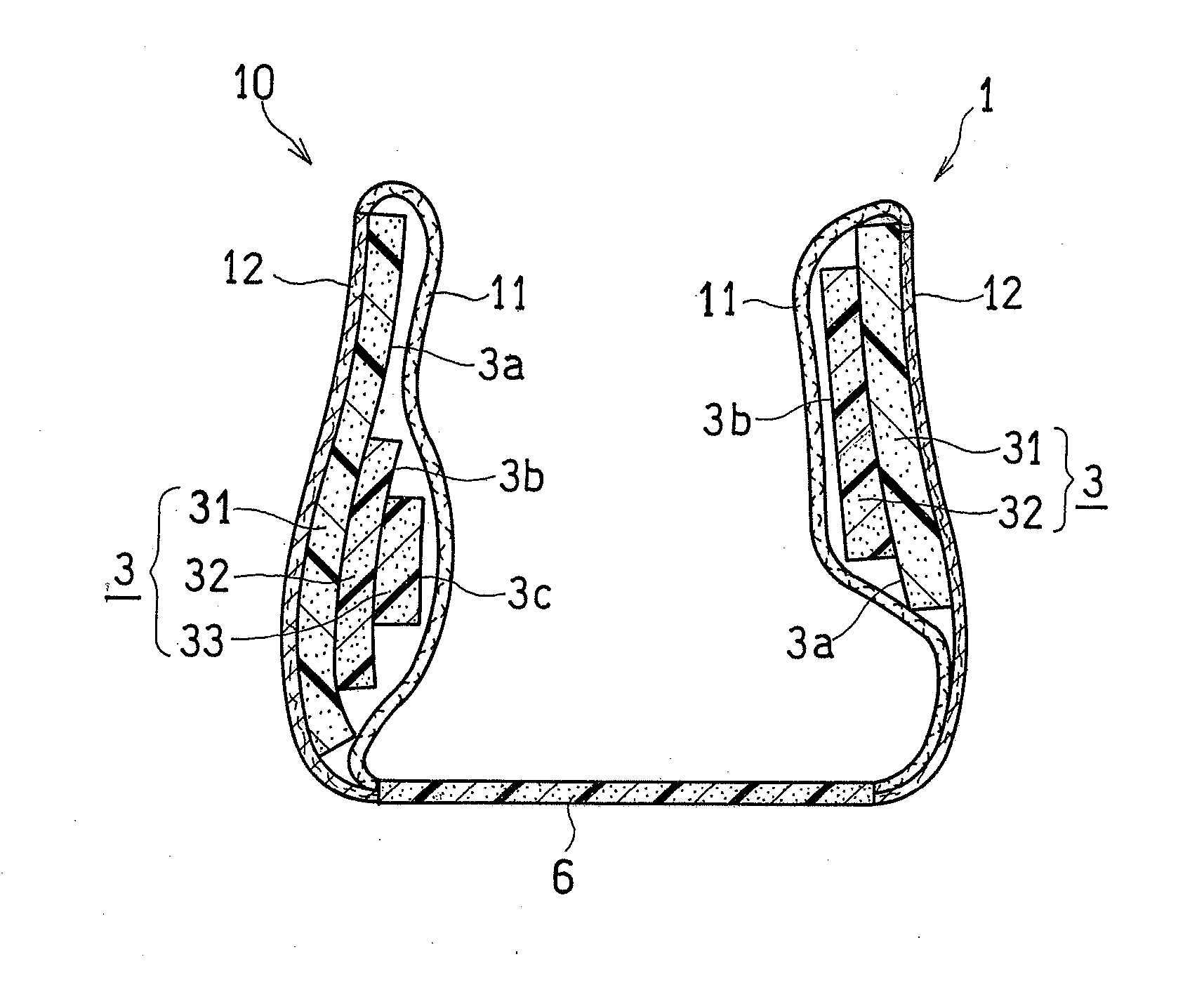
[0070]As shown in FIG. 4, the upper 1 includes the inner skin 11 placed on the wear's skin side, and the outer skin 12 placed on the opposite side from the inner skin 11. The sponge member 3 is housed between the inner skin 11 and the outer skin 12 in the heel portion 10.
[0071]Note that although the sponge member 3 undergoes substantial compressive deformation, or the like, when manufacturing the shoe, FIG. 4 merely shows the conceptual placement of the sponge member 3. Reference numeral 6 denotes an insole.
[0072]The inner skin 11 may be a mesh material, or the like, as well as a woven material or a knit material having desirable stretchability and air-permeability. On the other hand, the outer skin 12 may be a mesh material, or the like, as well as a plate or tape material made of a synthetic leather or a non-foamed synthetic resin having a desirable shape retention.
[0073]Note that each of the inner skin 11 and the outer skin 12 may include a single l...
embodiment 3
FIGS. 7A to 7D Show Embodiment 3
[0092]In the present embodiment, the third sponge plate 33 is absent. In such a case, the thickness of the first and second sponge plates 31 and 32 is preferably made greater than that in Embodiments 1 and 2.
[0093]In various embodiments, the thickness of the sponge plates 31 and 32 is preferably about 5 to 15 mm, and more preferably about 7 to 12 mm.
[0094]As shown in FIG. 7A, in Embodiment 3, the second sponge plate 32 has a narrowed portion 38 that is narrowed downwardly in the area of the center line CL. The narrowed portion 38, in cooperation with the narrowed portion 36, will further unlikely causes compression on the Achilles tendon.
[0095]As shown in FIGS. 7A, 7C and 7D, the second sponge plate 32 has a significantly larger area on the medial side portion 34 than on the lateral side portion 35. The second sponge plate 32 extends to a point anterior to the posterior end Ab of the medial ankle A1 on the medial side portion 34 of FIG. 7C, and the se...
embodiment 4
FIGS. 8A to 8D Show Embodiment 4
[0096]In this example, the medial side portion 34 and the lateral side portion 35 have shapes that are generally in line symmetry with each other about the center line CL.
[0097]In the present embodiment, the medial side portion 34 of the first sponge plate 31 covers at least a portion of the lower edge Ce of the calcaneal bone Ca directly below the talus Ta. On the other hand, the lateral side portion 35 of the first sponge plate 31 covers an area of the calcaneal bone Ca directly above the point O, wherein the point O is a bisector between the lower end of the lateral ankle A0 and the lower edge Ce of the calcaneal bone Ca.
[0098]The second sponge plate 32 of FIG. 8A includes, at its opposite ends, protruding portions 39 and 39 that coincide with the upper edge line of the first sponge plate 31. The protruding portions 39 will be helpful in positioning the first sponge plate 31 and the second sponge plate 32 with each other.
[0099]The sponge member 3 o...
PUM
 Abstract
Description
Claims
Application Information
 - R&D
- Intellectual Property
- Life Sciences
- Materials
- Tech Scout
- Unparalleled Data Quality
- Higher Quality Content
- 60% Fewer Hallucinations
Browse by: Latest US Patents, China's latest patents, Technical Efficacy Thesaurus, Application Domain, Technology Topic, Popular Technical Reports.
© 2025 PatSnap. All rights reserved.Legal|Privacy policy|Modern Slavery Act Transparency Statement|Sitemap|About US| Contact US: help@patsnap.com


