Eureka AIR delivers breakthrough ideas for toughest innovation challenges, trusted by R&D personnel around the world.

Power plant for a vehicle

Active Publication Date: 2015-10-15
NISSAN MOTOR CO LTD
View PDF14 Cites 2 Cited by
  • Summary
  • Abstract
  • Description
  • Claims
  • Application Information

AI Technical Summary

Benefits of technology

The invention allows for the conversion of electric motor vibrations into a swinging movement, which helps to reduce vibrations in the power plant. This is achieved by using an anchor point to diffuse the force received from the electric motor.

Problems solved by technology

However, as a result of thorough investigations into the vibration characteristics obtained using the above configuration, a new problem was discovered in that, if the gusset is improperly arranged, vibration of the electric motor caused by engine vibration is transmitted back to the engine block via the gusset, whereby vibration of the power plant may increase.

Method used


Image

  • Power plant for a vehicle
  • Power plant for a vehicle
  • Power plant for a vehicle

Examples


embodiment 1

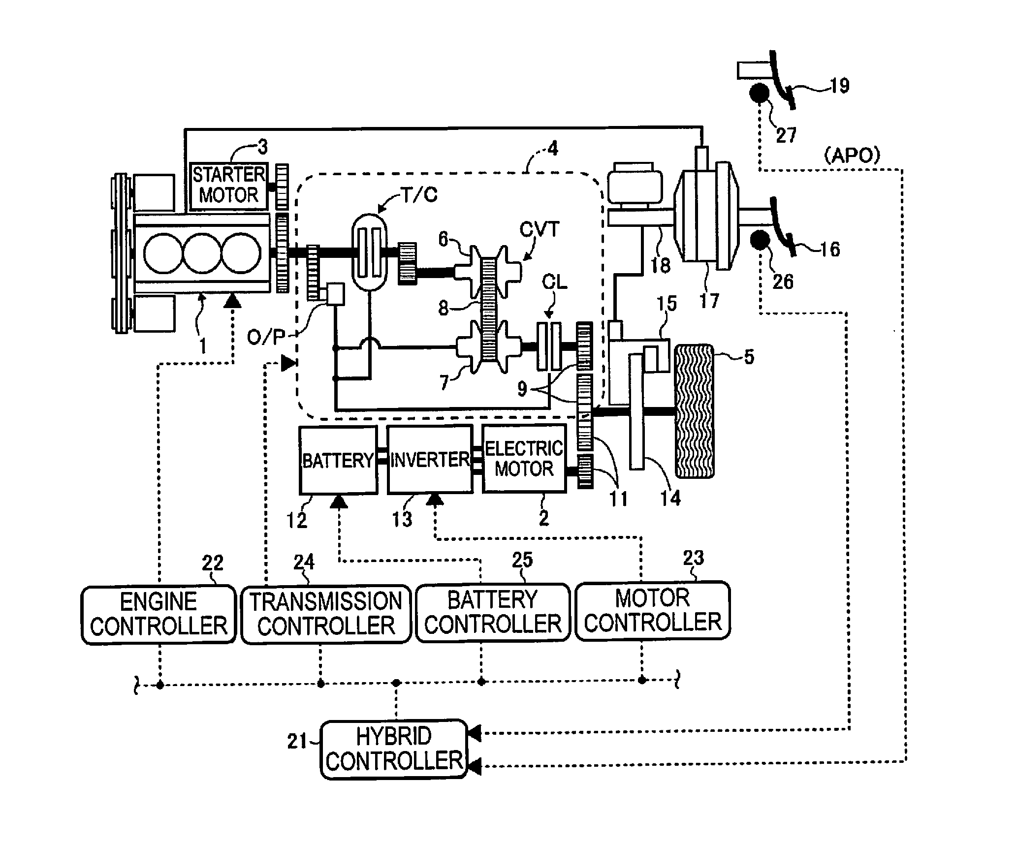
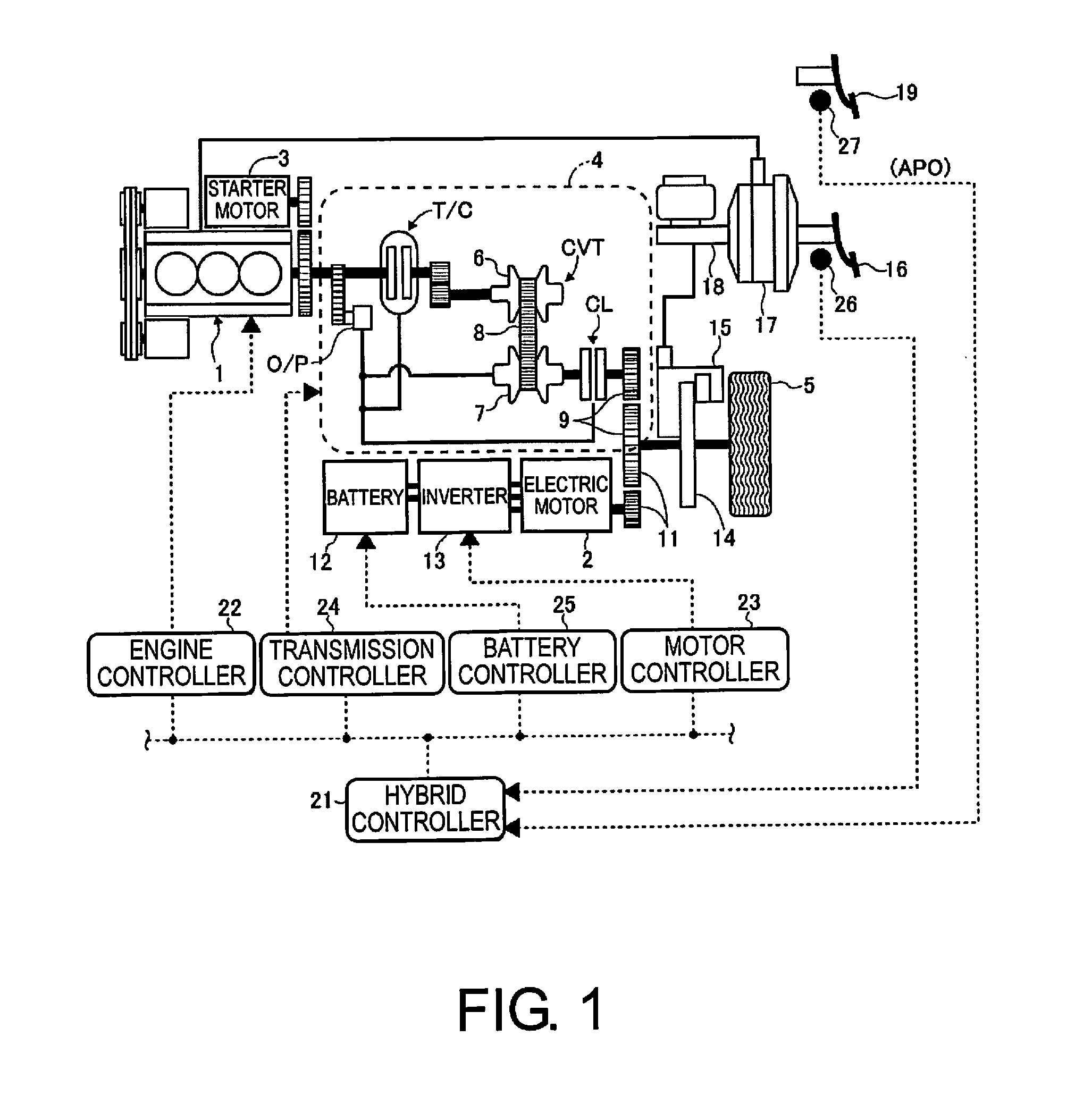
[0021]FIG. 1 is a schematic diagram of a drive train of a hybrid vehicle equipped with the power plant for a vehicle according to embodiment 1, and a system for controlling the entirety of the drive train. An engine 1 and an electric motor 2 are mounted in the hybrid vehicle of FIG. 1 as power sources, the engine 1 being started by a starter motor 3. The engine 1 is drive-coupled to a drive wheel 5 via a V-belt-type continuously variable transmission 4 so as to be able to be decoupled as appropriate from the drive wheel 5. A generic description of the V-belt-type continuously variable transmission 4 is given below.

[0022]The V-belt-type continuously variable transmission 4 is a continuously variable transmission CVT configured from a variator comprising a primary pulley 6, a secondary pulley 7, and a V-belt 8 bridging the pulleys 6, 7. The primary pulley 6 is linked to a crankshaft, which is an output shaft of the engine 1, interposed by a torque converter T / C to which a lock-up clut...

embodiment 2

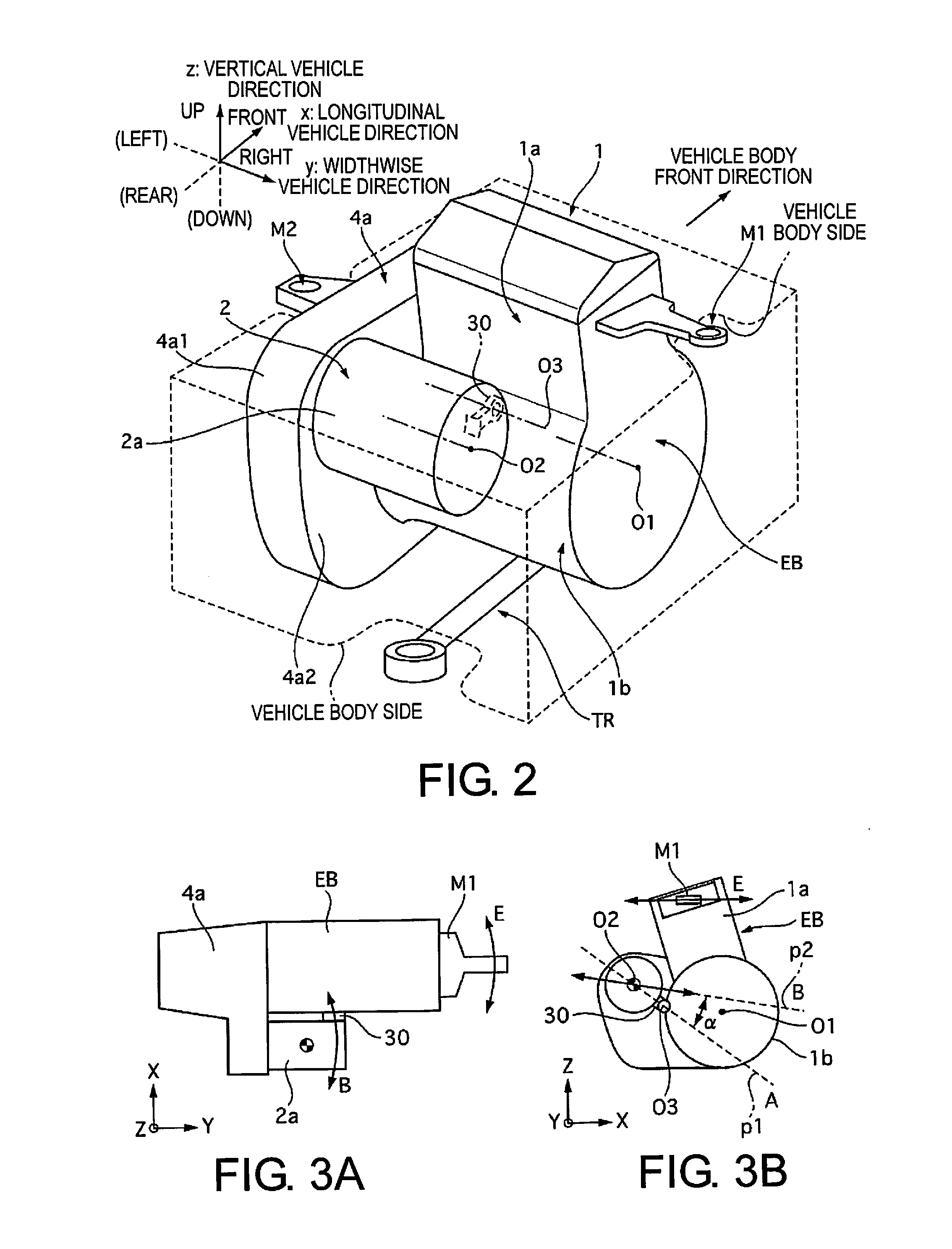
[0058]Next, embodiment 2 will be described. The basic configuration is the same as in embodiment 1; therefore, only points of difference will be described. FIGS. 9A and 9B are schematic views of the power plant for a vehicle of embodiment 2. FIG. 9A is a plan view viewed in the z direction, and FIG. 9B is a side view viewed in the y direction. In embodiment 1, when viewed in the z direction, the gusset 30 is disposed so as to be perpendicular to the crankshaft 01 (or the motor rotating shaft 02). However, embodiment 2 differs in that, when viewed in the z direction, the first line p1 is configured so as to intersect a plane F orthogonal to the crankshaft 01 and inclusive of the center of gravity of the electric motor 2, the first line p1 intersecting the plane F at an angle β that is smaller than angle α.

[0059]The action of the vibration in the present embodiment when viewed in the y direction is fundamentally the same as in embodiment 1; therefore, the action when viewed in the z d...


PUM


Abstract

A power plant for a vehicle of the present invention includes an electric motor attached to a transmission housing attached to an engine. The electric motor is attached to the side of the transmission housing toward the engine and is connected to the engine interposed by an anchor point. When the engine is viewed in a crankshaft direction, a line connecting the anchor point and the center of gravity of the electric motor intersects a line extending along a direction in which the electric motor vibrates due to vibration of the engine in the absence of an anchor point.

Description

CROSS-REFERENCE TO RELATED APPLICATIONS[0001]This application is a U.S. National stage application of International Application No. PCT / JP2013 / 078961, filed Oct. 25, 2013, which claims priority to JP Patent Application No. 2012-260552 filed on Nov. 29, 2012, the contents of each of which are hereby incorporated herein by reference.BACKGROUND[0002]1. Field of the Invention[0003]The present invention relates to a power plant for a vehicle in which at least an engine is mounted.[0004]2. Background Information[0005]The vehicle described in JP Patent No. 3584680 is an example of a vehicle of such description. This vehicle comprises an engine and an electric motor as a power plant, and is of a type such that the engine is coupled to drive wheels via a continuously variable transmission and the electric motor is constantly linked to the drive wheels. In this vehicle, because sufficient support cannot be ensured merely by cantilevering the electric motor using the continuously variable tran...

Claims


Application Information

Patent Timeline
IPC IPC(8): B60K6/48F02D29/02B60K6/40
CPCB60K6/48B60K6/40Y10S903/951B60K2006/4825F02D29/02B60K1/00B60K5/04B60K5/1216B60K6/26B60K6/543B60K2006/4808B60Y2200/92B60Y2400/72Y02T10/62B60K17/04
Inventor ABE, YUTAKAYAMAMOTO, KAZUYUKI
Owner NISSAN MOTOR CO LTD
Why Eureka
Eureka Blog
Learn More