Braking device for vehicle designed to achieve smooth deceleration

a technology of braking device and vehicle, which is applied in the direction of brake system, vehicle components, braking components, etc., can solve the problems of hysteresis, difference between the target value and the actual value of pressure difference, lack of flow rate of brake fluid output from differential pressure control valve, etc., and achieve the effect of reducing the deterioration of the driver's braking feeling

Inactive Publication Date: 2015-10-15
DENSO CORP +1
View PDF8 Cites 10 Cited by
  • Summary
  • Abstract
  • Description
  • Claims
  • Application Information

AI Technical Summary

Benefits of technology

[0022]Specifically, the brake device serves to control the wheel cylinder pressure so as to rise gradually without sharply changing it with an increase in the brake manipulated variable. This eliminates deterioration of a driver's braking feeling arising from a variation in deceleration of the vehicle and ensures smooth deceleration of the vehicle intended by the driver.

Problems solved by technology

However, the activation of the electric motor at a speed required to bring the pressure difference to be developed by the differential pressure control valve into agreement with a target value may result in a difference between the target value and an actual value of the pressure difference.
This is because an increase in discharged flow rate of the pump will result in a restricted flow rate of the brake fluid passing through the differential pressure control valve, which leads to a lack in flow rate of the brake fluid outputted from the differential pressure control valve.
There is, however, a hysteresis, as illustrated in FIG. 6, between when the pressure difference is being increased by increasing the quantity of current to be supplied to the differential pressure control valve and when the pressure difference is being decreased by decreasing the quantity of current to be supplied to the differential pressure control valve.
When the ratio of the pressure loss to a required pressure difference is great, for example, in a low-deceleration range, it may result in a failure in achieving the required pressure difference due to the response lag arising from the hysteresis.
It may be difficult to give the driver of the vehicle a good braking feeling, particularly, when the driver actuates the brake gently.
This will result in a sharp change in speed of the motor in response to a change in stroke of the brake pedal (which will also be referred to as a pedal stroke below), which leads to the pressure loss, as described above.
The pressure loss results in a rapid change in flow rate of the brake fluid discharged from the pump, thereby causing the degree of deceleration of the vehicle to vary, giving the driver a feeling of discomfort.
This makes the driver feel uncomfortable.
Basically, the technique of determining the volume V of the brake fluid required to develop the controlled pressure corresponding to the pedal stroke S and calculating the speed of the motor required to achieve the volume V results in a difficulty in ensuring the comfort of the braking operation.

Method used


Image

  • Braking device for vehicle designed to achieve smooth deceleration
  • Braking device for vehicle designed to achieve smooth deceleration
  • Braking device for vehicle designed to achieve smooth deceleration

Examples


first embodiment

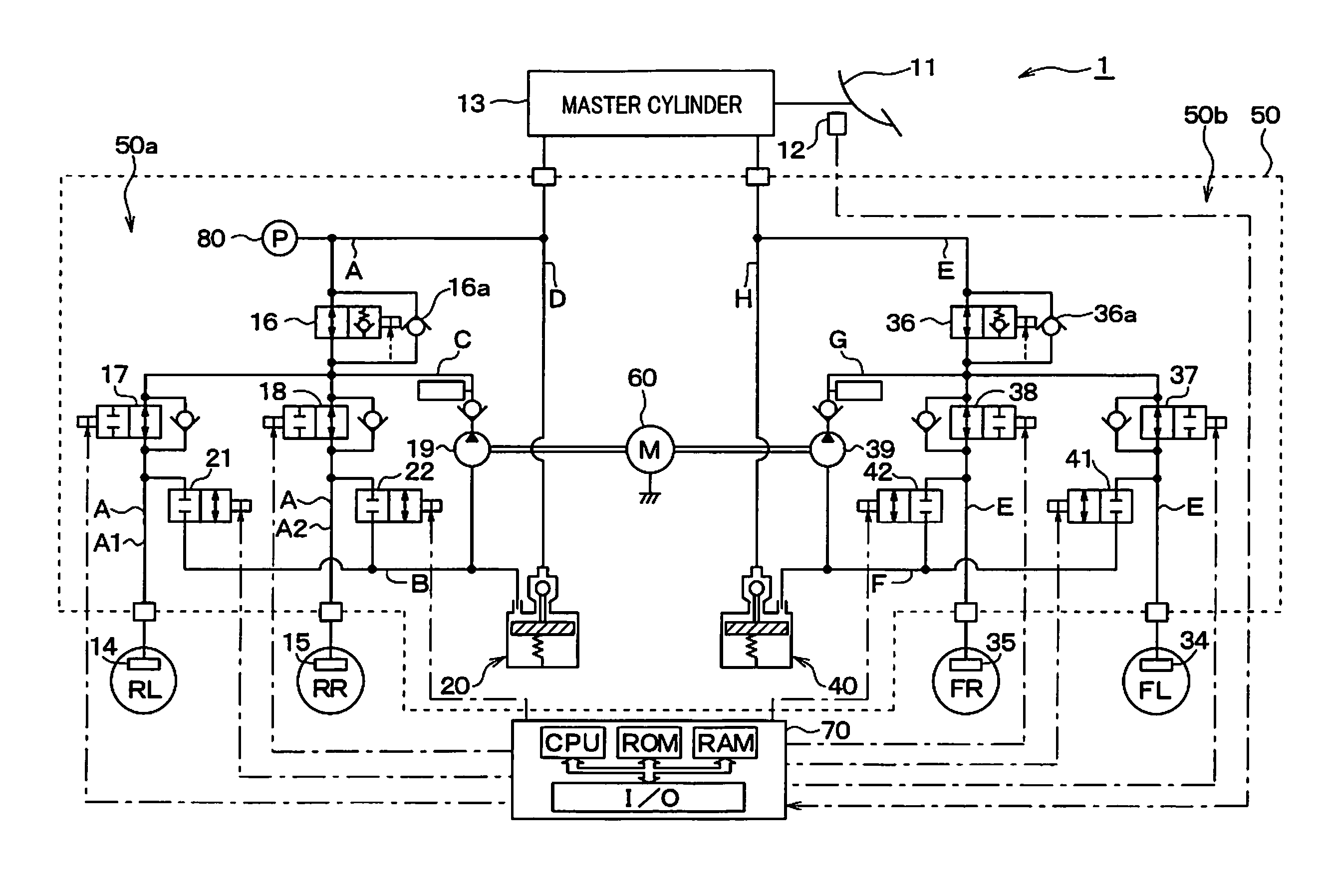
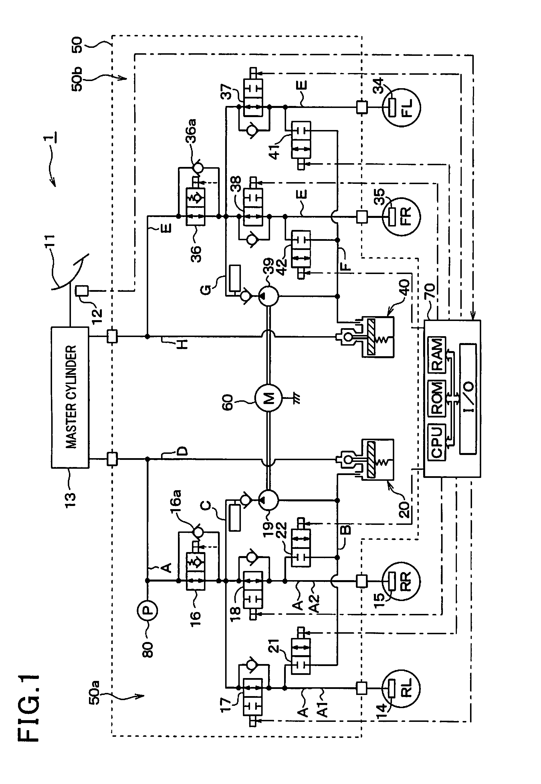
[0043]Referring to FIG. 1, there is shown a brake system equipped according to the first embodiment of the invention. The brake system, as referred to herein, is used with an automotive vehicle equipped with a so-called front / rear split hydraulic system, but may be employed with a diagonal split hydraulic system which includes two brake hydraulic circuits one of which controls the right front and the left rear wheel and the other of which controls the left front and the right rear wheel.

[0044]The brake system includes a brake device 1 which is equipped with a brake pedal 11 (i.e., a brake actuating member) to be depressed by a vehicle occupant or driver for applying the brakes to the vehicle, a stroke sensor 12, a master cylinder 13, wheel cylinders 14, 15, 34, and 35, and a brake pressure control actuator 50. When the driver depresses the brake pedal 11, the stroke sensor 12 works as a brake manipulated variable determiner to detect a degree to which the brake pedal 11 is manipulat...


PUM


Abstract

A brake device for a vehicle is equipped with an electric motor which drives a pump to deliver brake fluid to a wheel cylinder installed in a wheel of the vehicle. The brake device works to control pressure of the brake fluid in the wheel cylinder for creating a target braking force. In response to an increase in stroke of a brake pedal, the brake device elevates the pressure in the wheel cylinder gradually without sharply changing it. This eliminates deterioration of a driver's braking feeling arising from a variation in deceleration of the vehicle and ensures smooth deceleration of the vehicle intended by the driver of the vehicle.

Description

CROSS REFERENCE TO RELATED DOCUMENT[0001]The present application claims the benefit of priority of Japanese Patent Application No. 2014-81903 filed on Apr. 11, 2014, the disclosure of which is incorporated herein by reference.BACKGROUND OF THE INVENTION[0002]1 Technical Field of the Invention[0003]This disclosure relates generally to a brake system for vehicles which works to produce a braking force with the aid of a pump driven by an electric motor in response to an amount by which a brake actuating member is manipulated.[0004]2 Background Art[0005]Japanese Patent First Publication No. 2013-6529 teaches a brake system for an automotive vehicle which is engineered to actuate an electric motor to drive a pump for controlling a brake installed in the vehicle.[0006]The brake system is equipped with a differential pressure control valve disposed in a pipe connecting between a master cylinder (also referred to as an M / C below) and a wheel cylinder (also referred to as a W / C below) to con...

Claims


Application Information

Patent Timeline
Patent Type & Authority Applications(United States)
IPC IPC(8): B60T8/172B60T8/34
CPCB60T8/34B60T8/172B60T8/4072
Inventor TAKEUCHI, KIYOHITOMORISHITA, KAZUYA
Owner DENSO CORP
Why Eureka
Try Eureka