Rotor blade

a technology of rotating blades and rotating blades, applied in the field of rotating blades, can solve the problems of considerable aerodynamic loss of the flat tip geometry, and achieve the effect of improving the cooling of the tip

Inactive Publication Date: 2015-10-15
ROLLS ROYCE PLC
View PDF10 Cites 14 Cited by
  • Summary
  • Abstract
  • Description
  • Claims
  • Application Information

AI Technical Summary

Benefits of technology

[0028]The cooling gallery may be substantially parallel to the floor of the gutter in a region proximal to the exit. Arranging the cooling gallery to be substantially parallel to the floor of the gutter permits the cooling gallery and/or the cooling passage

Problems solved by technology

The simplest un-shrouded blade has a flat tip geometry, but this flat tip geo

Method used


Image

  • Rotor blade
  • Rotor blade
  • Rotor blade

Examples


Embodiment Construction

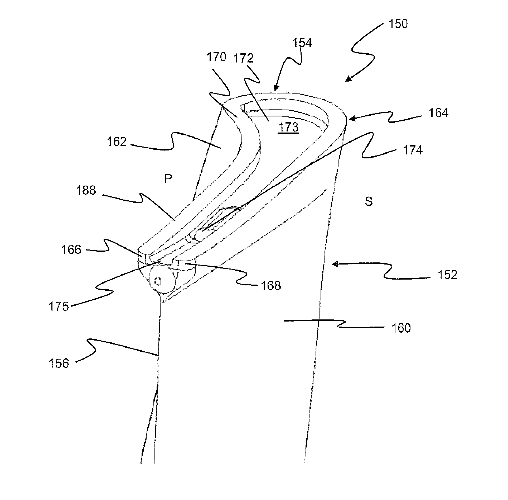
[0043]With reference to FIG. 3 a bypass gas turbine engine is indicated at 10. The engine 10 comprises, in axial flow series, an air intake duct 11, fan 12, a bypass duct 13, an intermediate pressure compressor 14, a high pressure compressor 16, a combustor 18, a high pressure turbine 20, an intermediate pressure turbine 22, a low pressure turbine 24 and an exhaust nozzle 25. The fan 12, compressors 14, 16 and turbines 20, 22, 24 all rotate about the major axis of the gas turbine engine 10 and so define the axial direction of the gas turbine engine.

[0044]Air is drawn through the air intake duct 11 by the fan 12 where it is accelerated. A significant portion of the airflow is discharged through the bypass duct 13 generating a corresponding portion of the engine thrust. The remainder is drawn through the intermediate pressure compressor 14 into what is termed the core of the engine 10 where the air is compressed. A further stage of compression takes place in the high pressure compress...


PUM


Abstract

A turbine blade has a trailing end and a leading end and a tip. A gutter is formed in the tip and extends to an exit defined in a region of the trailing end of the blade. The gutter is defined at least in part by a floor, and the floor defines a decreased depth in a region proximal to the exit than in a region distal to the exit.

Description

FIELD OF INVENTION[0001]The present invention relates to a rotor blade, in particular but not exclusively, a turbine blade and / or a gas turbine engine.BACKGROUND[0002]Gas turbine engines are typically employed to power aircraft. Typically a gas turbine engine will comprise a fan driven by an engine core. The engine core is generally made up of one or more turbines (e.g. high pressure and intermediate pressure turbines) which drive respective compressors via coaxial shafts. The fan is usually driven off an additional lower pressure turbine in the engine core.[0003]A turbine of a gas turbine engine includes a rotor with one or more blades arranged circumferentially around the rotor; the blades may be mounted or welded to the rotor. There are two general types of blades for the high pressure turbine: shrouded and un-shrouded. At the high operating temperatures and cycle loadings of modern day engines, the un-shrouded blade has been found to be preferable for the high pressure turbine. ...

Claims


Application Information

Patent Timeline
IPC IPC(8): F01D5/14F01D5/18
CPCF01D5/145F01D5/187F05D2250/52F05D2240/307F05D2220/32F01D5/20Y02T50/60
Inventor DAWSON, JOHNMILLI, ANDREASELLERS, PAUL ANDREW
Owner ROLLS ROYCE PLC
Why Eureka
Try Eureka