
Machine tool diagnostic method and system

a technology of machine tools and diagnostic methods, applied in the direction of computer control, program control, instruments, etc., can solve the problems of machine tool time-related changes and mechanical damage, wear and degradation, and prolong the downtime of machine tools, so as to prevent the reduction of diagnostic accuracy

Inactive Publication Date: 2015-10-15
MITSUBISHI HEAVY IND MACHINE TOOL CO LTD
View PDF3 Cites 31 Cited by
  • Summary
  • Abstract
  • Description
  • Claims
  • Application Information

AI Technical Summary

Benefits of technology

The present invention is a machine tool diagnosis system that uses data from operation patterns to diagnose machine tool states, resulting in a high accuracy diagnosis. The system uses initial data to create a training set, and re-measured data to create a test set. The system uses a specific method called 1 class SVM to diagnose machine tool aging degradation and faults separately. By preventing decreases in diagnostic accuracy, the system can effectively diagnose machine tool states and maintain machining precision.

Problems solved by technology

Machine tools experience time-related changes and mechanical damage such as wear and degradation with use.
However, once an anomaly such as an abnormal stoppage or irregular sound occurs on a machine tool, there is a need to ascertain the cause, to obtain or fabricate replacement parts, or even to perform corrective construction, thereby lengthening machine tool downtime.
Therefore when a sample data set is divided into multiple clusters, even abnormal data between clusters ends up being contained inside the unit space.
As a result, in the Mahalanobis method there is a potential that abnormal data will be misdiagnosed as normal.

Method used

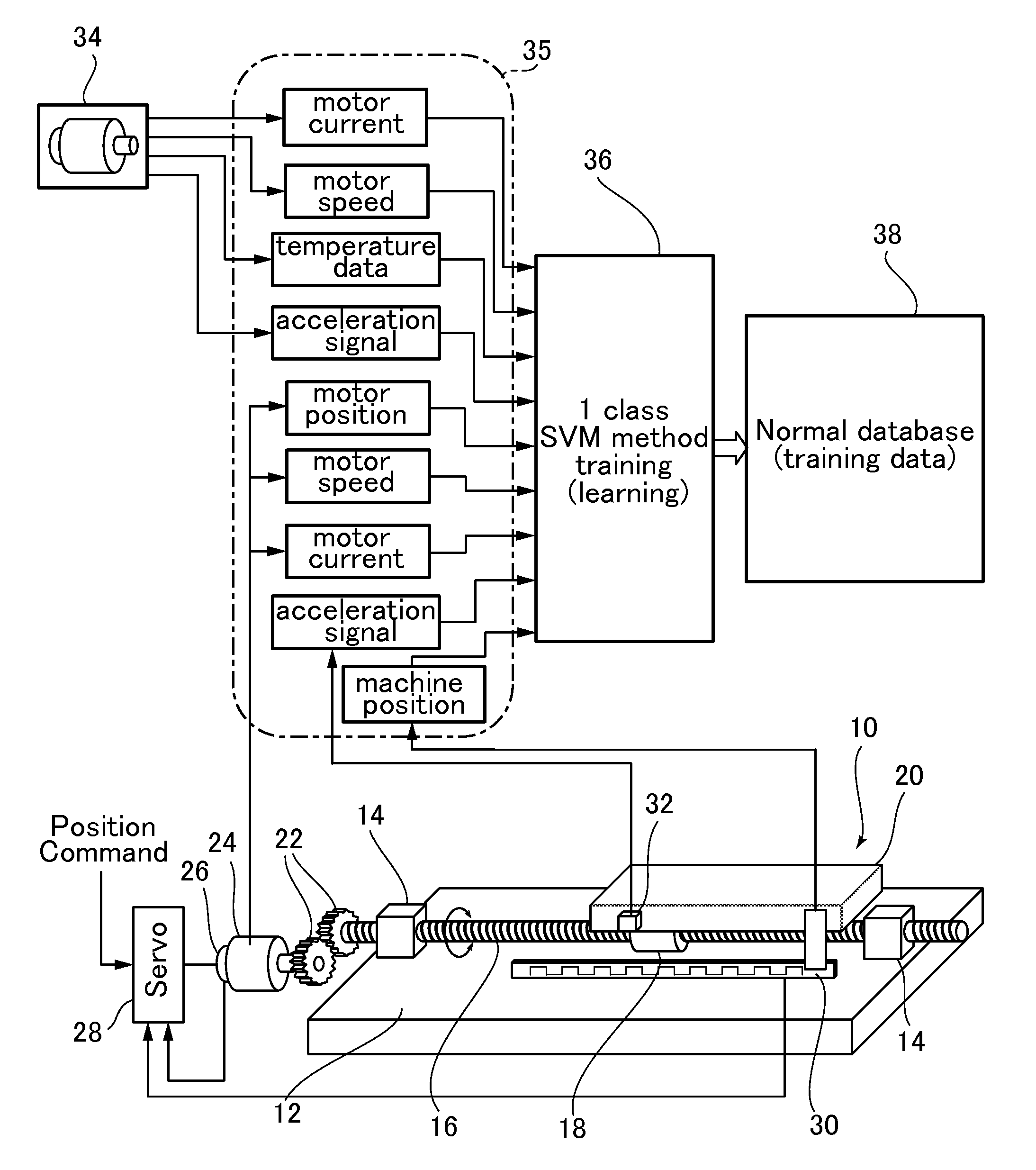

Image

  • Machine tool diagnostic method and system
  • Machine tool diagnostic method and system
  • Machine tool diagnostic method and system

Examples


second embodiment

[0075]Next, referring to FIG. 5, we explain a

[0076]In the second embodiment, an operating pattern for machining mass produced workpieces such as screws or gears is adopted as the operating pattern at the time when machine tool training data and test data are acquired. Therefore in the second embodiment a mapping space normal area is generated in normal database 52, based on training data acquired during operation in a mass-production workpiece machining operation pattern.

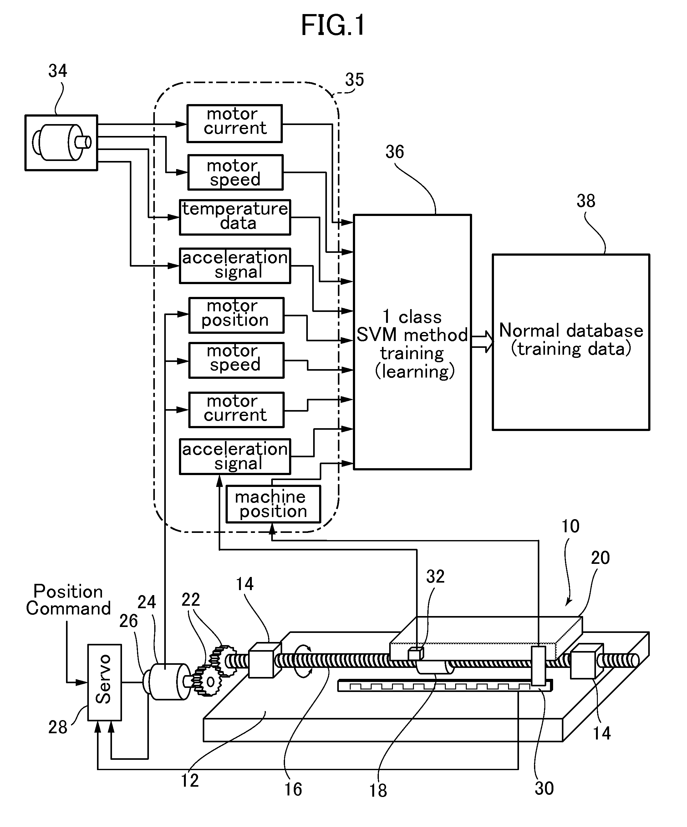
[0077]In normal database 52, 1 class SVM method mapping space information, in which normal area C has been generated by training when machining a mass produced machined product, is stored in normal database 38.

[0078]In the second embodiment, the test data also employs the same operating pattern used at the time of machining mass produced workpieces. In the same manner as the first embodiment, test data is input into the SVM discriminator and a diagnostic result (f(x)) value is computed by diagnostic unit 51.

[0079]A ...

third embodiment

[0082]Next, referring to FIG. 6, we explain a

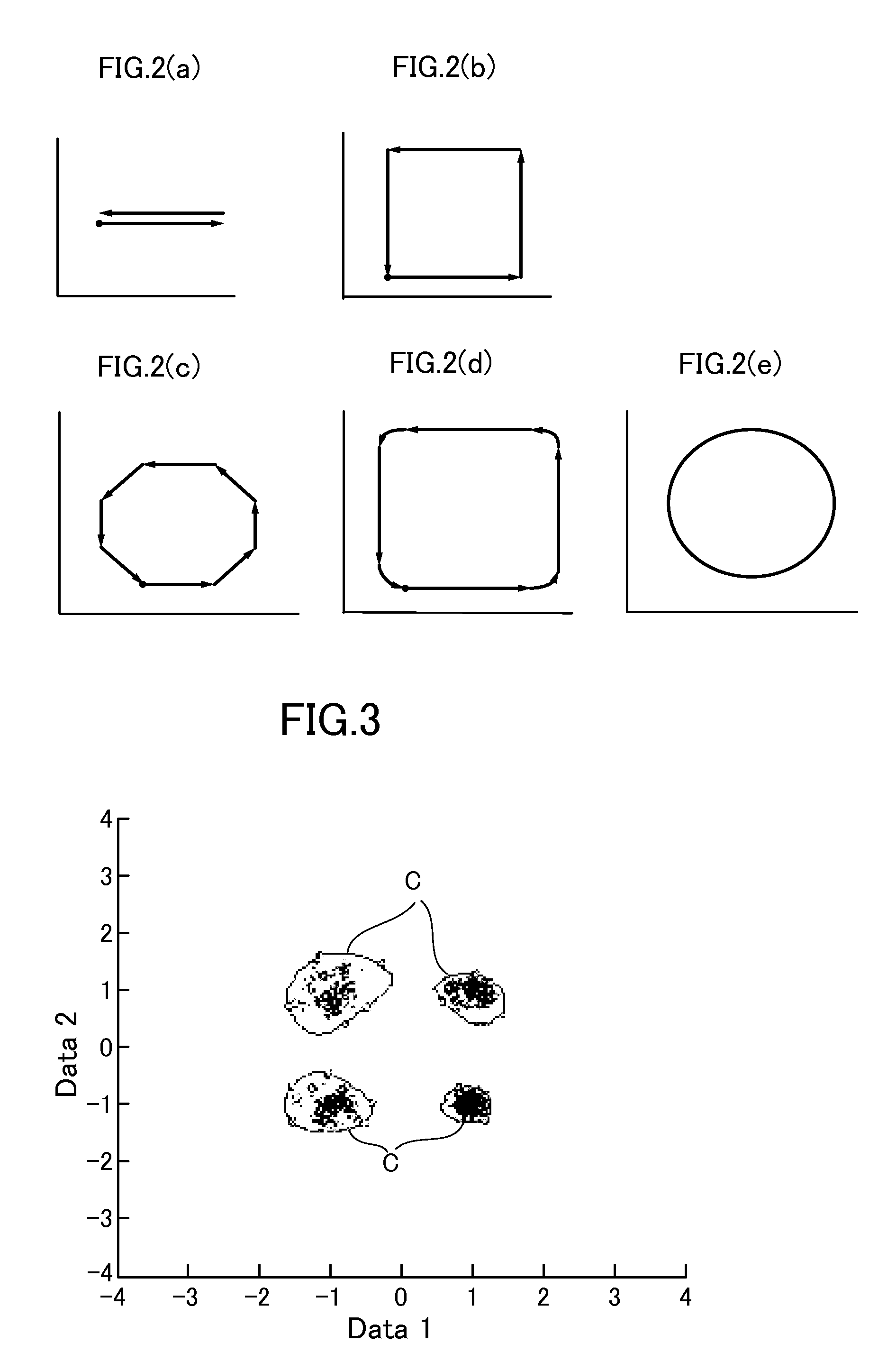
[0083]FIG. 6 is an explanatory diagram of a failure timing prediction based on diagnostic results; the horizontal axi s shows time and the vertical axi s shows SVM discriminator diagnostic result (f(x)) values. These diagnostic result (f(x)) value correspond to the position of test data in the mapping space, such as that shown in FIG. 3. The more the diagnostic result (f(x)) value approaches zero from a positive value, the more the test data position approaches, from inside normal area C in FIG. 3, the boundary line between normal area C and the abnormal area. When the training data (f(x)) value is zero, the test data is positioned on the boundary line. Moreover, if the value of training data (f(x)) is negative, the test data is position outside normal area C.

[0084]The FIG. 6 curve I connects with solid lines a plot of the diagnostic results (f(x)) when multiple iterations of test data are input to an SVM discriminator from machine tool s...

fifth embodiment

[0092]Next, referring to FIG. 8, we explain a

[0093]In the FIG. 5 embodiment, test data is used as additional training data to generate a new normal area in a new mapping space of the 1 class support vector machine method. Information for the 1 class SVM method mapping space in which this new normal area is generated is stored in the latest normal database 82.

[0094]Note that updating of this latest database 82 by the addition of training data can be done regularly or irregularly.

[0095]Also, initial training information based on training data at time of shipment is left in the time-of-shipment normal database 85.


PUM


Abstract

A machine tool diagnostic method includes: an initial acquisition step for acquiring initial measurement data by measuring multiple parameters of the machine tool while operating the machine tool in a predetermined operating pattern; a generating step for generating a normal area in a mapping space of a 1 class support vector machine method using the initial measurement data as training data; a reacquisition step in which, after operating the machine tool, the multiple parameters are measured to acquire re-measured data while again operating the machine tool in the predetermined operating pattern; and a diagnostic step for diagnosing the machine tool using the re-measured data as test data, based on whether or not the test data is contained in the normal area of the mapping space in the 1 class support vector machine method.

Description

BACKGROUND OF THE INVENTION[0001]1. Field of the Invention[0002]The present invention pertains to a machine tool diagnostic method and system, and more particularly to a diagnostic method and system for diagnosing machine tools using a 1 class support vector machine (SVM).[0003]2. Description of Related Art[0004]Machine tools experience time-related changes and mechanical damage such as wear and degradation with use. For this reason, regular inspections and part replacements were performed with the object of preventing sudden malfunctions or stoppage of the machine tool. However, once an anomaly such as an abnormal stoppage or irregular sound occurs on a machine tool, there is a need to ascertain the cause, to obtain or fabricate replacement parts, or even to perform corrective construction, thereby lengthening machine tool downtime. Therefore various technology has been proposed, as disclosed in Patent Document 1 (Japanese Unexamined Patent Application Publication No. 2013-164386),...

Claims


Application Information

Patent Timeline
IPC IPC(8): G05B19/4065G06N99/00G06N20/10
CPCG06N99/005G05B19/4065B23Q17/007G06N20/10G05B2219/37212G06N20/00
Inventor YAMAMOTO, HIDEAKIFUJISHIMA, YASUO
Owner MITSUBISHI HEAVY IND MACHINE TOOL CO LTD
Learn More