Vehicle brake control device

a brake control and vehicle technology, applied in the direction of braking systems, instruments, analogue processes for specific applications, etc., can solve the problems of difficult to keep the pressure-increasing valve slightly open, abnormal noise, and provide uncomfortable feeling to the driver, so as to reduce the current value, reduce the variation of vehicle deceleration, and enhance the effect of driver comfor

Active Publication Date: 2015-10-22
TOYOTA JIDOSHA KK
View PDF13 Cites 12 Cited by
  • Summary
  • Abstract
  • Description
  • Claims
  • Application Information

AI Technical Summary

Benefits of technology

[0013]According to another aspect of the present invention, the hydraulic control unit controls energization of the independent hydraulic control valve to increase a current value with a predetermined gradient from a start current lower than a valve-opening current that is a current value upon opening the closed independent hydraulic control valve when a hydraulic adjustment start condition is established, and to decrease the current value when a hydraulic adjustment stop condition is established, and the valve-opening timing matching prevention unit sets different start currents for the independent hydraulic control valve (44FL) corresponding to the left wheel and the independent hydraulic control valve (44FR) corresponding to the right wheel (S22, S32).
[0014]In the present invention, when a hydraulic adjustment start condition is established, the hydraulic control unit controls energization of the independent hydraulic control valve to increase a current value with a predetermined gradient from a start current lower than a valve-opening current. The independent hydraulic control valve is opened with the increase in the applied current. Thus, the hydraulic pressure of the wheel cylinder is adjusted. In this case, a value of a current flowing through the independent hydraulic control valve is increased from a start current lower than a valve-opening current with a predetermined gradient, whereby the independent hydraulic control valve can slowly be opened. Accordingly, the hydraulic pulsation that is likely to occur at the moment of opening the valve can be suppressed. After a hydraulic adjustment stop condition is established, the hydraulic control unit controls energization of the independent hydraulic control valve to decrease the current value. With this, the independent hydraulic control valve is closed to stop the flow of the operating fluid. The hydraulic adjustment start condition and the hydraulic adjustment stop condition may be set based on the magnitude of the deviation between a target hydraulic pressure and an actual hydraulic pressure (detected hydraulic pressure) of the wheel cylinder.
[0015]When the start current is set small upon controlling the energization of the independent hydraulic control valve, a time from when the current value is started to be increased till the independent hydraulic control valve is opened becomes long, with the result that the time from when the current value is started to be increased till the hydraulic adjustment stop condition is established also becomes long. On the contrary, when the start current is set large, the time from when the current value is started to be increased till the hydraulic adjustment stop condition is established becomes short. The present invention utilizes such situation. Specifically, the valve-closing timing matching prevention unit sets different start currents for the independent hydraulic control valve for the left wheel and for the independent hydraulic control valve for the right wheel to prevent the valve-closing timings of both independent hydraulic control valves from matching. Accordingly, the present invention can reduce the variation in the vehicle deceleration upon braking, thereby being capable of enhancing comfort for a driver.
[0016]The valve-closing timing matching prevention unit may include a configuration of setting a different amount (difference between the valve-opening current and the start current) by which the start current becomes smaller than the valve-opening current between the independent hydraulic control valve corresponding to the left wheel and the independent hydraulic control valve corresponding to the right wheel. This configuration can more precisely prevent the valve-closing timings of both independent hydraulic control valves from matching.
[0017]According to another aspect of the present invention, the hydraulic control unit controls energization of the independent hydraulic control valve to increase a current value with a predetermined gradient from a start current lower than a valve-opening current that is a current value upon opening the closed independent hydraulic control valve when a hydraulic adjustment start condition is established, and to decrease the current value when a hydraulic adjustment stop condition is established, and the valve-opening timing matching prevention unit sets a different timing at which the current value is increased from the start current between the independent hydraulic control valve (44FL) corresponding to the left wheel and the independent hydraulic control valve (44FR) corresponding to the right wheel (S33 to S36).
[0018]When the timing at which the current value is increased from the start current is the same between the left wheel and the right wheel upon controlling the energization of the independent hydraulic control valve, the valve-closing timing is also likely to be the same. In view of this, in the present invention, the valve-closing timing matching prevention unit sets a different timing of increasing the current value from the start current between the independent hydraulic control valve corresponding to the left wheel and the independent hydraulic control valve corresponding to the right wheel to prevent the valve-closing timings of both independent hydraulic control valves from matching. Accordingly, the present invention can reduce the variation in the vehicle deceleration upon braking, thereby being capable of enhancing comfort for a driver.

Problems solved by technology

In this case, when the pressure-increasing valve is suddenly opened, a hydraulic pulsation occurs, and this hydraulic pulsation is transmitted to pipes to cause abnormal noise.
However, once the pressure-increasing valve is opened, it is difficult to keep the pressure-increasing valve slightly opened due to inertia force of the operating fluid supplied from the accumulator.
Therefore, while the driver depresses the brake pedal, the variation in the deceleration continues, which might provide uncomfortable feeling to the driver.

Method used


Image

  • Vehicle brake control device
  • Vehicle brake control device
  • Vehicle brake control device

Examples


first embodiment

According to Deceleration Variation Prevention Control

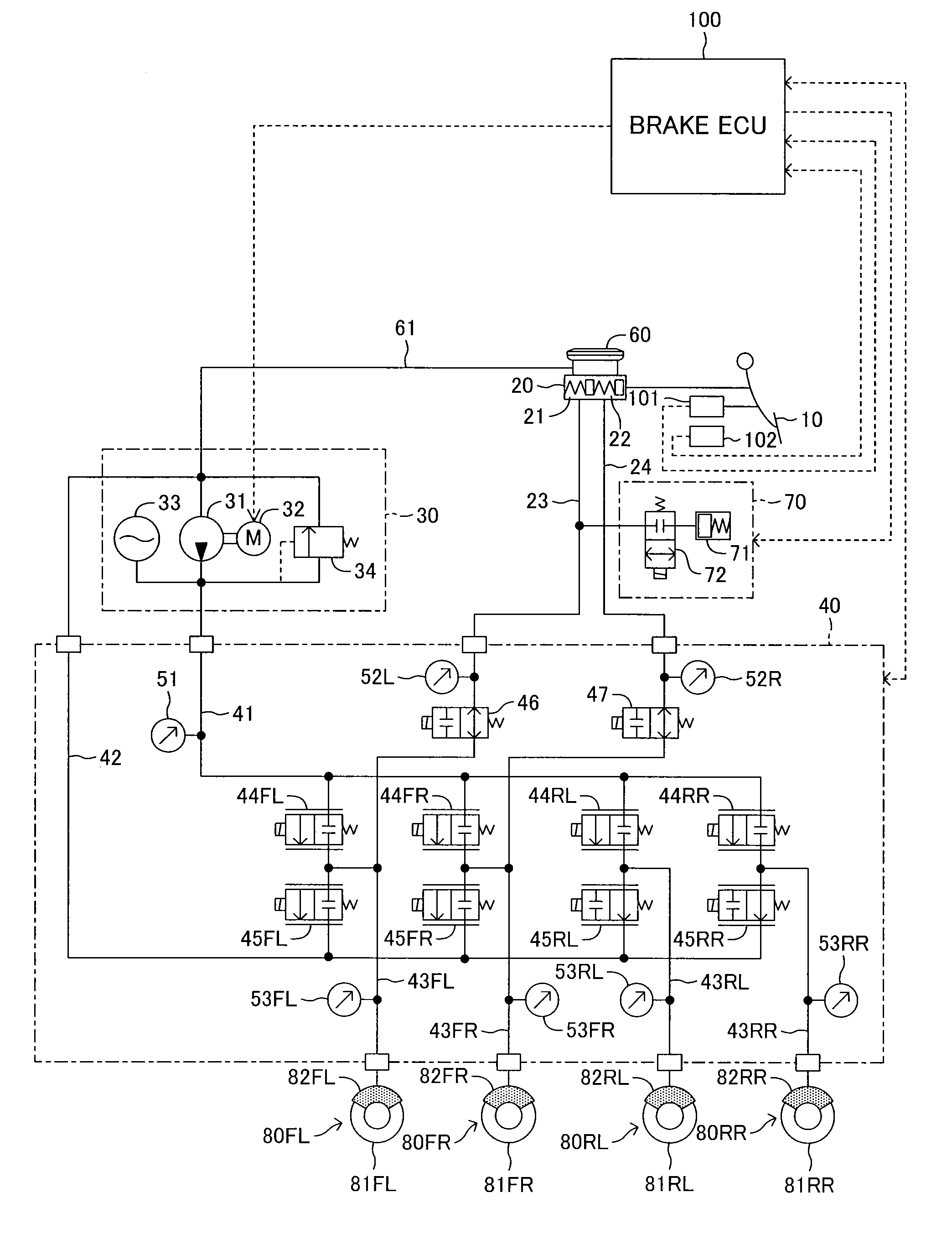
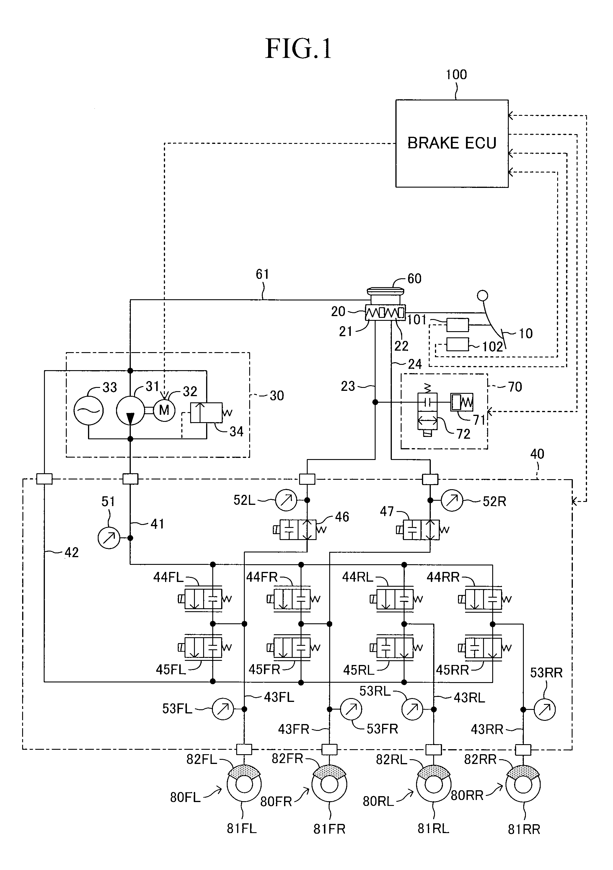
[0069]Subsequently, a deceleration variation prevention control will be described. The deceleration variation prevention control is executed when the target hydraulic pressure of the wheel cylinders 82 for the left and right wheels are the same.

[0070]When the brake pedal 10 is depressed, the pressure-increasing linear control valve 44 is opened to supply the operating fluid to the wheel cylinder 82 from the power hydraulic pressure generating device 30. When the pressure-increasing linear control valve 44 is sharply opened, pulsation of the hydraulic pressure of the operating fluid occurs to generate abnormal noise in a pipe. Such problem can be solved by slowly opening the pressure-increasing linear control valve 44 with a gradual increase in the value of the current flowing through the pressure-increasing linear control valve 44 from a value smaller than the valve-opening current. This energization control is referred to as a h...

second embodiment

According to Deceleration Variation Prevention Control

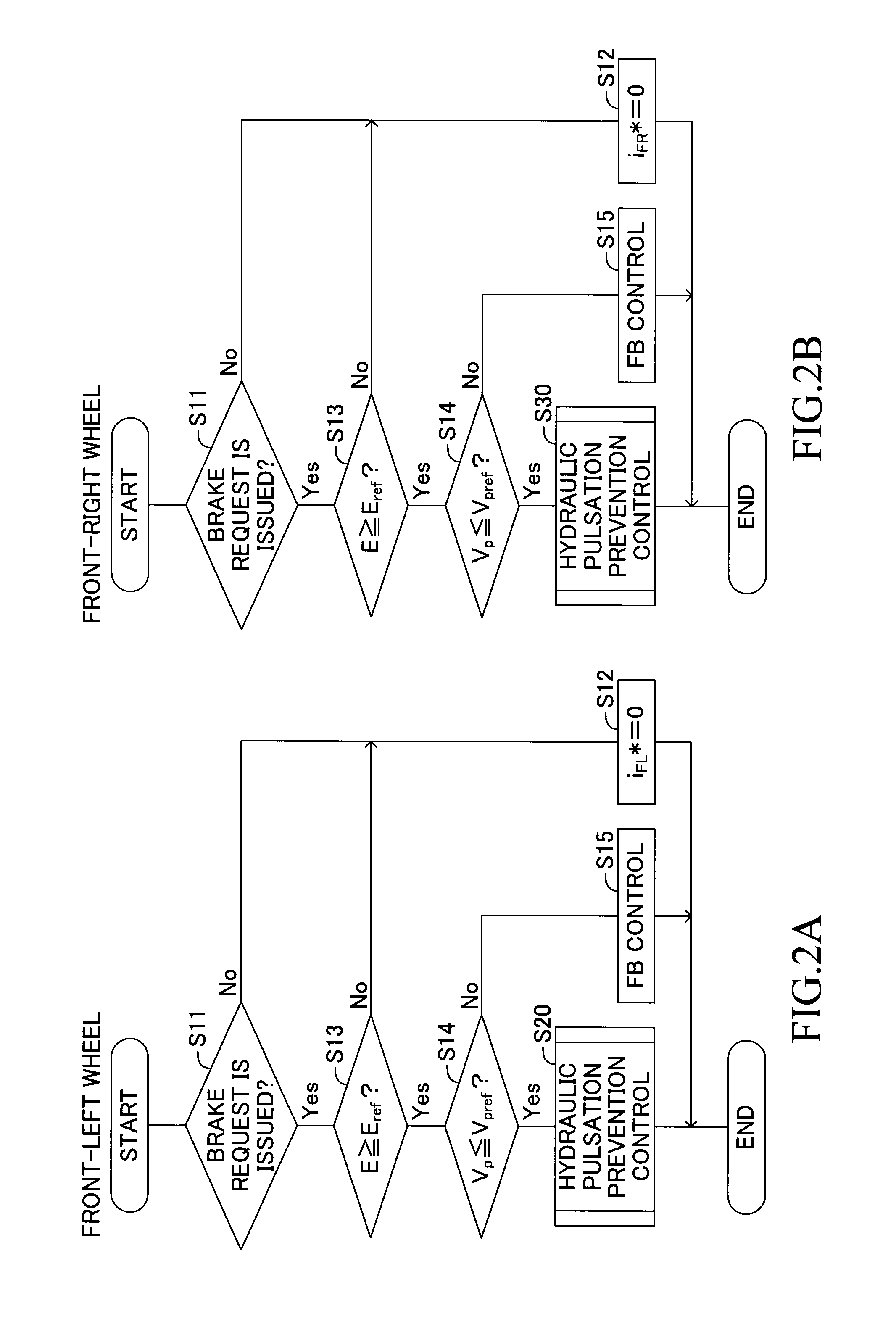
[0101]Next, a second embodiment of a deceleration variation prevention control will be described. In the first embodiment, the pressure-increasing linear control valves 44FL and 44FR are prevented from being closed at the same timing by using the decrease set values i1 and i2, in order to suppress the variation in the vehicle deceleration. On the other hand, in the second embodiment, the timing at which energization is started is shifted between the pressure-increasing linear control valves 44FL and 44FR in order to prevent the pressure-increasing linear control valves 44FL and 44FR from being closed at the same timing.

[0102]FIG. 5 illustrates the hydraulic pulsation prevention control subroutine for the front-right wheel according to the second embodiment. The hydraulic pulsation prevention control subroutine for the front-left wheel is the same as that in the first embodiment. In the hydraulic pulsation prevention control subro...


PUM


Abstract

When a brake pedal is slowly depressed, a brake ECU sets a target current iFL* of a pressure-increasing linear control valve for a front-left wheel to increase from a current value lower than a valve-opening current i open by a decrease set value i1, and sets a target current iFL* for a pressure-increasing linear control valve for a front-right wheel to increase from a current value lower than a valve-opening current i open by a decrease set value i2 (<i1). This prevents a timing at which the pressure-increasing linear control valve is closed and a timing at which the pressure-increasing linear control valve is closed from matching, whereby a variation in a vehicle deceleration G can be suppressed.

Description

TECHNICAL FIELD[0001]The present invention relates to a vehicle brake control device that controls a hydraulic pressure of a wheel cylinder by an electronic control apparatus.BACKGROUND ART[0002]A vehicle brake control device including a linear control valve on an operating-fluid flow path formed from a power hydraulic source to a wheel cylinder has conventionally been known, the device controlling energization of the linear control valve such that a hydraulic pressure of the wheel cylinder follows a target hydraulic pressure. For example, Patent Document 1 proposes a brake control device including a solenoid linear control valve (linear control valve including a pressure-increasing linear control valve and a pressure-decreasing linear control valve) for adjusting a hydraulic pressure for a wheel cylinder of each of front-left, front-right, rear-left, and rear-right wheels, wherein the hydraulic pressure of the wheel cylinder of each of the front-left, front-right, rear-left, and re...

Claims


Application Information

Patent Timeline
Patent Type & Authority Applications(United States)
IPC IPC(8): B60T8/17B60T8/40B60T8/171B60T8/36
CPCB60T8/17B60T8/171B60T8/4081B60T8/36B60T2270/604B60T8/3655
Inventor NIMURA, KAZUNORI
Owner TOYOTA JIDOSHA KK
Why Eureka
Try Eureka