Vehicle

a technology for vehicles and body frames, applied in the field of vehicles, can solve the problems that the body frame of vehicles is likely to interfere with the right front wheel and the left front wheel, and achieve the effect of small overall configuration and small siz

Active Publication Date: 2015-10-22
YAMAHA MOTOR CO LTD
View PDF9 Cites 17 Cited by
  • Summary
  • Abstract
  • Description
  • Claims
  • Application Information

AI Technical Summary

Benefits of technology

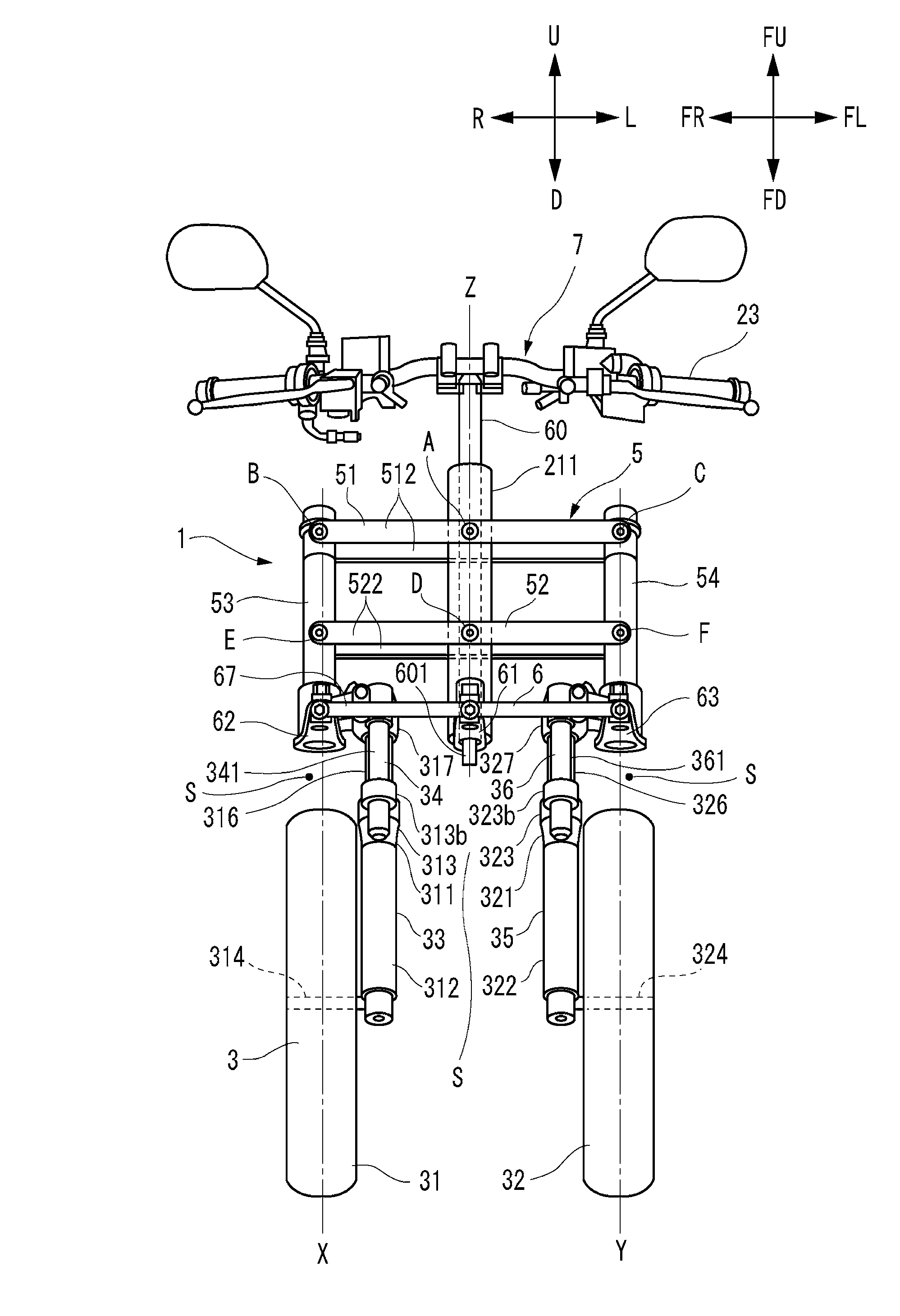
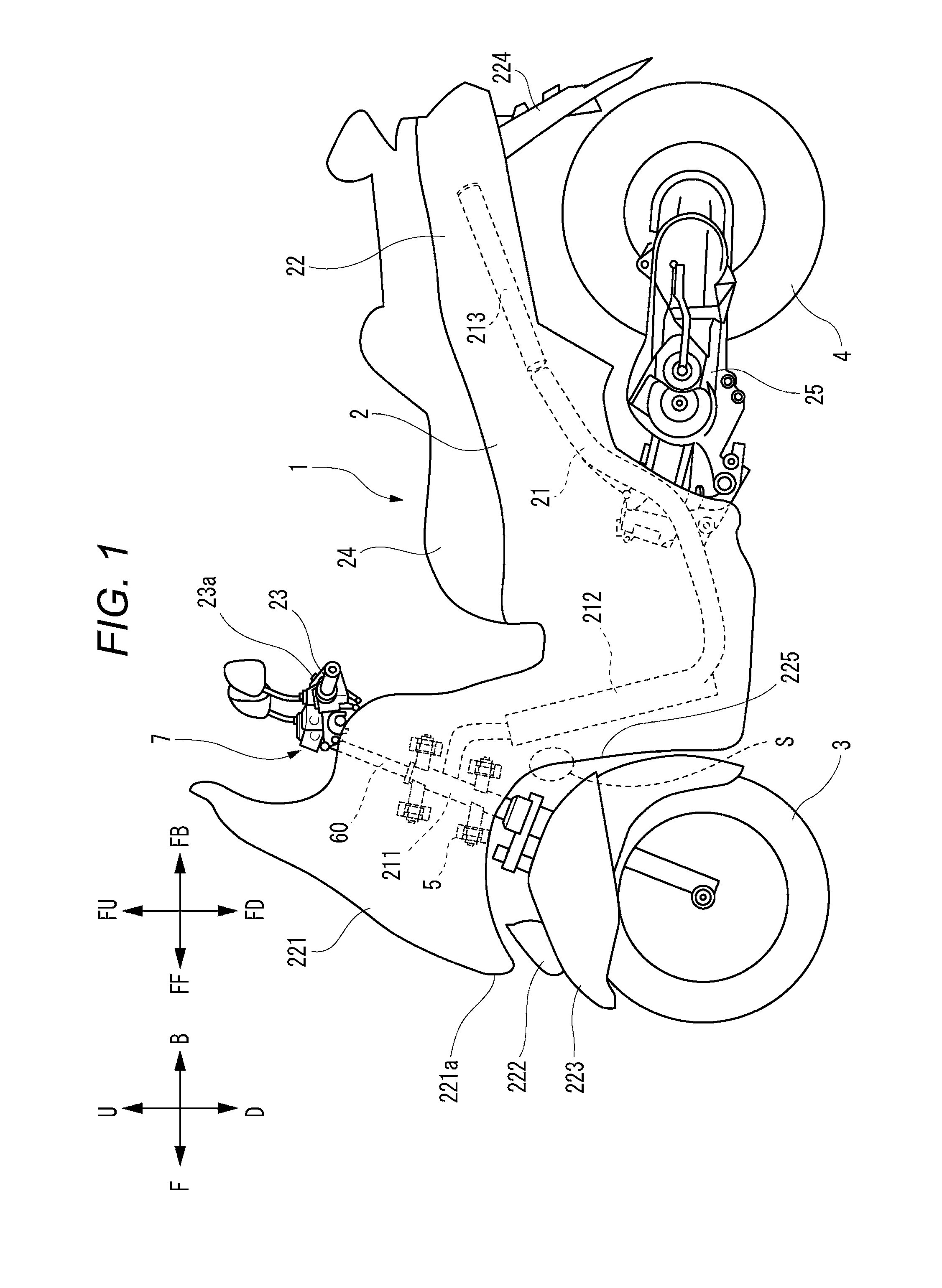
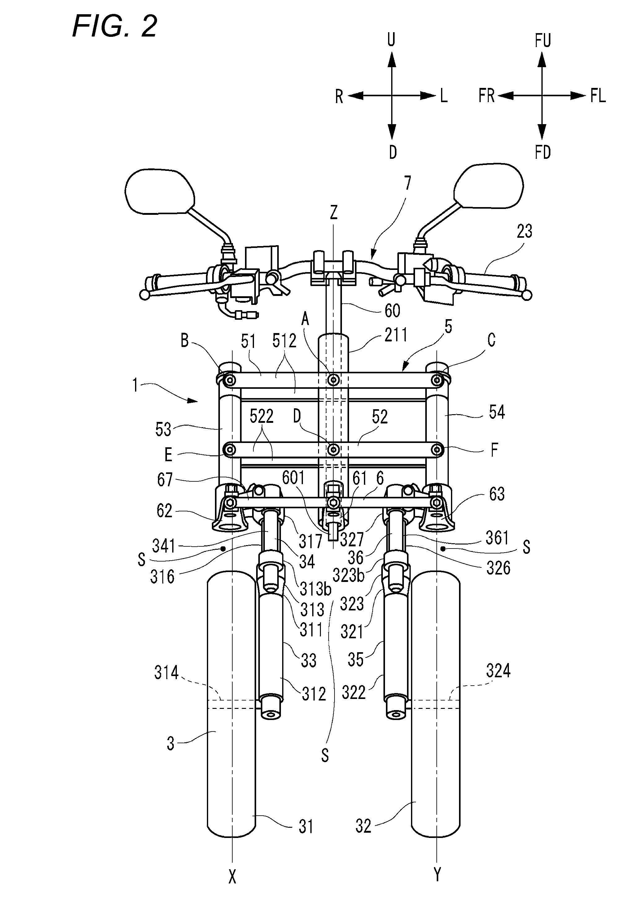
[0038]According to the configuration described above, incoming objects are deflected in the left-right direction of the vehicle body frame along the inclined portions of the right protecting portion and the left protecting portion. With this configuration, it is possible to prevent incoming objects from entering an area behind the right front wheel and the left front wheel. This enables the right protecting portion and the left protecting portion to be made even smaller in size. Consequently, the front portion of the vehicle is made smaller in size while ensuring the protecting function of the vehicle including the leanable vehicle body frame and the two front wheels against incoming objects.
[0039]Preferably, the vehicle is configured such that the right protecting portion covers at least a portion of an upper surface of the right front wheel, and provides at least a portion of a fender function that prevents objects including muddy water kicked up by the right front wheel from scattering; and the left protecting portion covers at least a portion of an upper surface of the left front wheel, and provides at least a portion of fender function that prevents objects including muddy water kicked up by the left front wheel from scattering.
[0040]According to the configuration described above, it is possible to prevent incoming objects from entering an area behind the right front wheel and the left front wheel. It is therefore possible to mak

Problems solved by technology

When the front end of the vehicle body cover is disposed behind the respective front ends of the right front wheel and the left front wheel provided within a narrow space so as to make the v

Method used


Image

  • Vehicle
  • Vehicle
  • Vehicle

Examples


Embodiment Construction

[0062]In the vehicle including the leanable vehicle body frame and the link mechanism, the right front wheel and the left front wheel each have a wide movable range. This is because the right front wheel and the left front wheel are turned when steered, are displaced in the up-down direction of the vehicle body frame as the right shock absorber and the left shock absorber extend or contract, and are displaced in the up-down direction of the vehicle body frame as the link mechanism operates. A vehicle body cover, which is configured so as not to be displaced relative to the vehicle body frame, preferably covers a long distance with respect to the right front wheel and the left front wheel, each of which has a wide movable range, so as to avoid interference therewith.

[0063]In the event that a front end of the vehicle body cover is disposed behind respective front ends of the right front wheel and the left front wheel arranged within a narrow space in order to make the vehicle body cov...


PUM


Abstract

A right front fender and a left front fender are displaceable relative to a vehicle body frame in accordance with an operation of a link mechanism. At least a portion of the right front fender is disposed above a center in the up-down direction between an upper end of a right front wheel and a lower edge of the link mechanism or a steering mechanism directly above the right front wheel, and is disposed below a right lower edge of a front portion of a link cover portion, as seen from a front in the front-rear direction of the vehicle body frame when the vehicle body frame is in the upright state. At least a portion of the left front fender is disposed above a center in the up-down direction between an upper end of a left front wheel and a lower edge of the link mechanism or the steering mechanism directly above the left front wheel, and is disposed below the left lower edge of the front portion of the link cover portion, as seen from the front when the vehicle body frame is in the upright state.

Description

BACKGROUND OF THE INVENTION[0001]1. Field of the Invention[0002]The present invention relates to a vehicle including a leanable vehicle body frame and two front wheels.[0003]2. Description of the Related Art[0004]A known vehicle includes a vehicle body frame that is leanable leftward or rightward when the vehicle is cornering, and two front wheels that are arranged side by side in a left-right direction of the vehicle body frame (for example, see U.S. Design Pat. No. D547,242 and U.S. Pat. No. 7,073,806).[0005]A front portion of this type of vehicle tends to be large. Thus, in the vehicles disclosed in U.S. Design Pat. No. D547,242 and U.S. Pat. No. 7,073,806, the link mechanism is disposed above the two front wheels so as to reduce the space therebetween, thus realizing a reduction in the size of the front portion of the vehicle in relation to the left-right direction of the vehicle body frame. However, in the vehicle including two front wheels arranged within a narrow space, the v...

Claims


Application Information

Patent Timeline
IPC IPC(8): B62D9/02B62K21/12B62J15/00B62D25/16B62K5/05
CPCB62D9/02B62D25/16B62K21/12B62J15/00B62K5/05B60G3/20B60G2200/144B60G2300/122B60G2300/45B62J17/02B62K5/027B62K5/08B62K5/10B62K2005/001B62J17/10
Inventor SASAKI, KAORUOHTA, MITSUAKI
Owner YAMAHA MOTOR CO LTD
Why Eureka
Try Eureka