High Speed Laser Processing of Transparent Materials

a laser processing and transparent material technology, applied in the direction of glass blowing apparatus, glass shaping apparatus, glass making apparatus, etc., can solve the problems of large kerf width, large kerf width, slow process speed, etc., and achieve high resolution, high precision laser, and avoid the effect of gaussian beam tight focusing regim

Active Publication Date: 2015-10-22
UAB ALTECHNA R&D
View PDF2 Cites 81 Cited by
  • Summary
  • Abstract
  • Description
  • Claims
  • Application Information

AI Technical Summary

Benefits of technology

[0032]Based on the above understanding, it is realized that the usage of large-angle Bessel-like beam may lead to peak fluences large enough to cause optical breakdown to occur. However, said breakdown may occur only in a very tiny and precisely localized volume, e.g. in cylindrical like volume around the beam axis having a diameter of the order of the laser wavelength, which therefore may absorb the laser light and becomes the source of strong shock waves, which serve to fabricate the material. However, due to the controlled energy amount coming to every point of the axis, the catastrophic behavior featuring the Gaussian beam tight focusing regime may be carefully avoided.
[0033]It is noted that the creation of elongated damage region formed by means of single pulses of Bessel-like laser beams, which may causes optical breakdown inside a needle-shaped volume, which is both very long (e.g. ≧50 μm, ≧100 μm, ≧300 μm, even ≧700 μm) and very thin (e.g. having a diameter ≦2 μm, ≦1.5 μm, ≦1 μm, even ≦0.5 μm), e.g. inside a needle-shaped volume having a length / diameter aspect ratio ≧25, ≧100, ≧500, even ≧1000, may provide for high precision laser cutting of transparent materials. This precision may be owed at least partly to the possibility of controlling the mechanism of energy transfer to matter, e.g. both for what concerns the control of the exact amount of energy needed to locally generate, in single shot, the shock pressure wave (i.e. the wave which is believed to produce the local modification of the material, e.g. the damaging, and / or the local creation of material stress) and for what concerns the control of the exact position in the transverse coordinate plane from which said pressure wave should be generated. Notably, in spite of the fact that the produced elongated damage region may feature a volume that is larger than the volume wherein the breakdown occurs (i.e. the volume wherein the electron plasma density exceed the critical value for absorption), the possibility of operating in single shot regime, i.e. in the absence of any thermal and or mechanical accumulation effect, plays in favor of creating a tiny needle shape damage volume too, e.g. having a diameter in the transverse plane which is not much larger than the diameter of the breakdown volume, e.g. ≦4 times, or ≦3 times, or even ≦2 times the diameter of the breakdown volume. In other terms, the diameter of the damage volume may be ≦2 times, or ≦1.5 times, or even ≦1 times larger than the diameter of the first zero intensity ring of the Bessel-like beam. The possibility of controlling with very high resolution both the transverse size and the position of the elongated damage zone is a key feature of the Bessel-like beam single-pulse laser cutting method of transparent material in the aim of improving the quality (e.g. the sharpness, the curvature, etc.) of the herein disclosed cutting process.

Problems solved by technology

According to WO 2012 / 006736 A1, in this optical breakdown domain the singulation, dicing, scribing, cleaving, cutting and facet treatment of transparent materials has disadvantages such as slow process speed, generation of cracks, contamination by ablation debris, and large kerf width.

Method used


Image

  • High Speed Laser Processing of Transparent Materials
  • High Speed Laser Processing of Transparent Materials
  • High Speed Laser Processing of Transparent Materials

Examples


Embodiment Construction

[0068]The following is a detailed description of exemplary embodiments of the present disclosure. The exemplary embodiments described therein and illustrated in the drawings are intended to teach the principles of the present disclosure, enabling those of ordinary skill in the art to implement and use the present disclosure in many different environments and for many different applications. Therefore, the exemplary embodiments are not intended to be, and should not be considered as, a limiting description of the scope of patent protection. Rather, the scope of patent protection shall be defined by the appended claims.

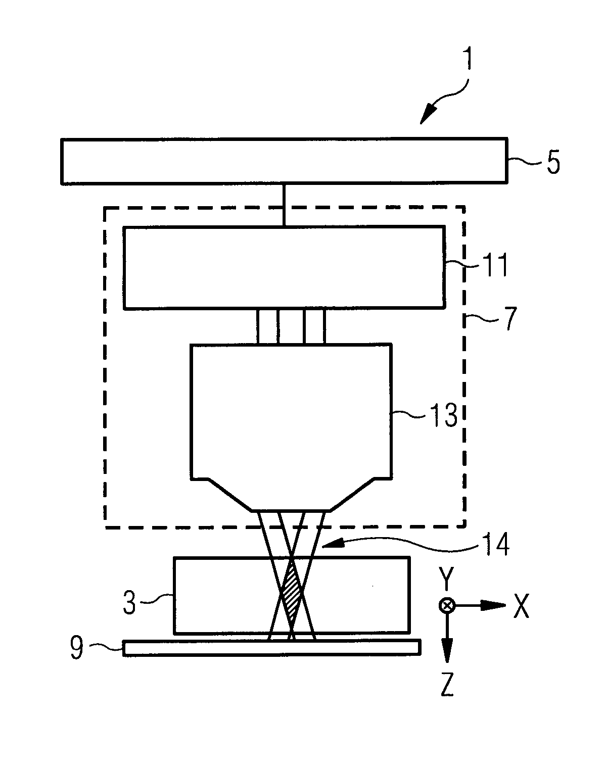
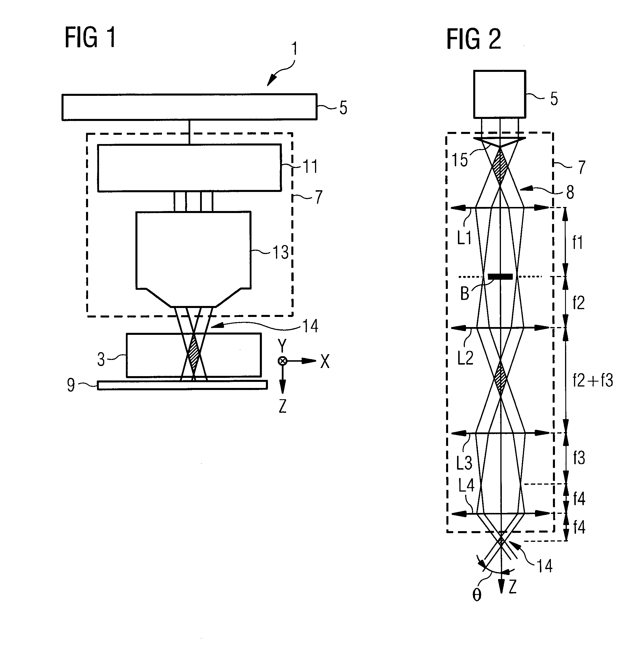
[0069]The disclosure is based in part on the realization that interaction of laser light with a material may restructure the material along the laser propagation direction, and, for example, result in modified regions within the material, herein also referred to as elongate (internal) damage regions. Providing those internal modified regions along a separation line over...


PUM

PropertyMeasurementUnit
aspect ratioaaaaaaaaaa
distanceaaaaaaaaaa
conical half-angleaaaaaaaaaa

Abstract

A method and system for laser pre-cutting a layered material (31) with a laser beam (14) is disclosed. The layered material (31) comprises at least one tensile stress layer (TSL), at least one compression stress layer (CSL1, CSL2), and at least one interface region (IR1, IR2) between the at least one tensile stress layer (TSL) and the at least one compression stress layer (CSL1, CSL2) and is transparent to allow propagation of the laser beam (14) through the layered material (31). The method may comprise setting an optical beam path (8) and a laser characteristic of the laser beam (14) such that an interaction of the laser beam (14) with the layered material (31) generates an elongate damage region (57) in the layered material (31), and, for each of a series of pre-cut positions (XN−1, XN, XN+1) of the layered material (31), pre-cutting the layered material (31) by positioning the layered material (31) and the laser beam (14) with respect to each other and irradiating the laser beam (14) such that the respective elongate damage regions (57) extend across the at least one interface region (IR1, IR2).

Description

TECHNICAL FIELD[0001]The present disclosure relates generally to laser cutting of transparent materials such as glass, and more particularly to laser cutting using Bessel-like beam configurations.BACKGROUND[0002]Laser processing of material, specifically the controlled interaction of laser light with material, is well established in various fields of applications such as laser cutting and laser welding, be it, for example, in industrial as well as medical applications. The interaction depends on the laser light parameters such as wave length, focus zone, laser power etc. as well as the material properties such as absorption at the respective wave length, band gap of the material etc. In combination, those parameters and properties define the interaction that takes place and in particular the field strength that is provided at a specific position within the material. A thermal approach is disclosed in US 2009 / 0294419 A1 using a system for laser scoring of non-flat materials based on ...

Claims


Application Information

Patent Timeline
Patent Type & Authority Applications(United States)
IPC IPC(8): C03B33/02B23K26/40B23K26/00
CPCC03B33/0222B23K26/4075B23K26/0087B23K26/40B23K26/359B23K26/53B23K2103/50C03B33/033
Inventor BHUYAN, MANOJ K.JEDRKIEWICZ, OTTAVIADI TRAPANI, PAOLOSABONIS, VYTAUTASMIKUTIS, MINDAUGAS
Owner UAB ALTECHNA R&D
Why Eureka
Try Eureka