Multi-purpose micro-trench insert

a micro-trench and insert technology, applied in special-purpose vessels, instruments, transportation and packaging, etc., can solve the problems of unprotected conduits and fiber optic cables, relatively significant surface defects, and easy damage, and achieves easy installation, easy bonding, and added strength and stability.

Inactive Publication Date: 2015-10-22
SUPERGROUT PRODS
View PDF4 Cites 37 Cited by
  • Summary
  • Abstract
  • Description
  • Claims
  • Application Information

AI Technical Summary

Benefits of technology

[0016]The aspects disclosed herein provide various advantages. For example, the structural filler is lightweight and easy to install prior to back filling the micro-trench with a polymeric material. The structural filler eliminates the need for unreliable, expensive, and labor consuming clips to prevent the conduit from floating within the polymeric material because of buoyancy or expansion due to heat generated by the curing process of polyurea backfill. The structural filler also reduces the required amount of back fill by up to 50% and a

Problems solved by technology

However, the exponential growth of fiber optic cables has created challenges as to how to manage and install this new technology so that its capabilities can be easily provided to all areas.
One disadvantage of current grout materials is that they can suffer shrinkage as they harden or over time, which can lead to relatively significant surface defects as well as to a relatively high amount of consolidation both of which are too significant for success as a micro-trench grout application.
This can also leave the conduit and the fiber optic cables housed therein unprotected and susceptible to damage.
Due to the issues associated with cementitious grout materials, other fillers for micro-trenching have been explored, but they also suffer from some limitations.
A couple of significant disadvantages have arisen with regard to this proposed technique.
The resulting trench is u

Method used


Image

  • Multi-purpose micro-trench insert
  • Multi-purpose micro-trench insert
  • Multi-purpose micro-trench insert

Examples


Embodiment Construction

[0023]Detailed examples of the present disclosure are disclosed herein; however, it is to be understood that the disclosed examples are merely exemplary and may be embodied in various and alternative forms. It is not intended that these examples illustrate and describe all possible forms of the disclosure. Rather, the words used in the specification are words of description rather than limitation, and it is understood that various changes may be made without departing from the spirit and scope of the disclosure.

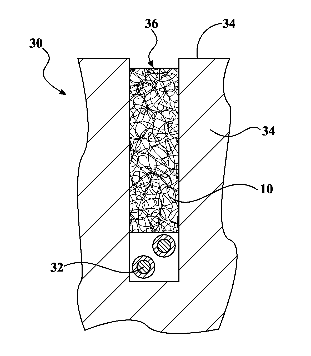
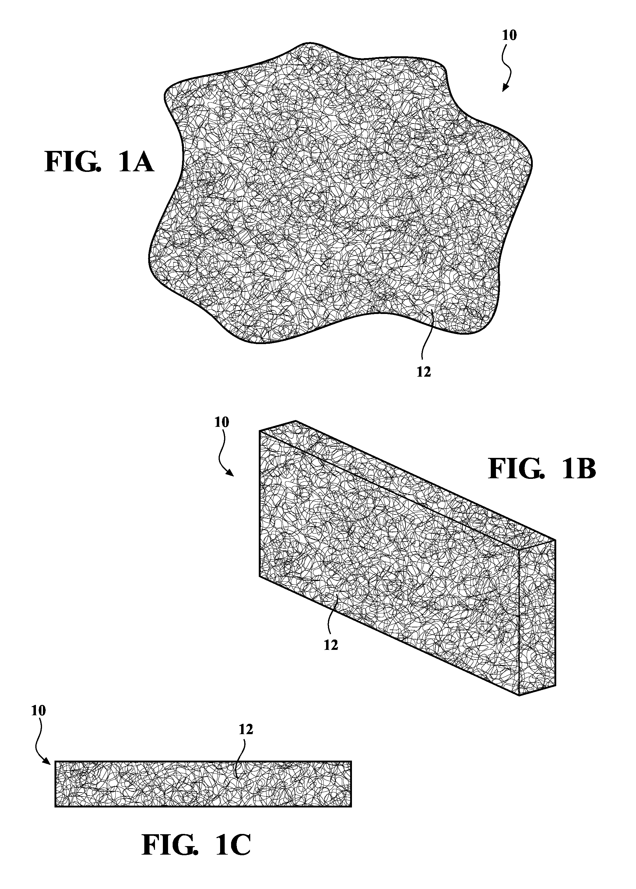
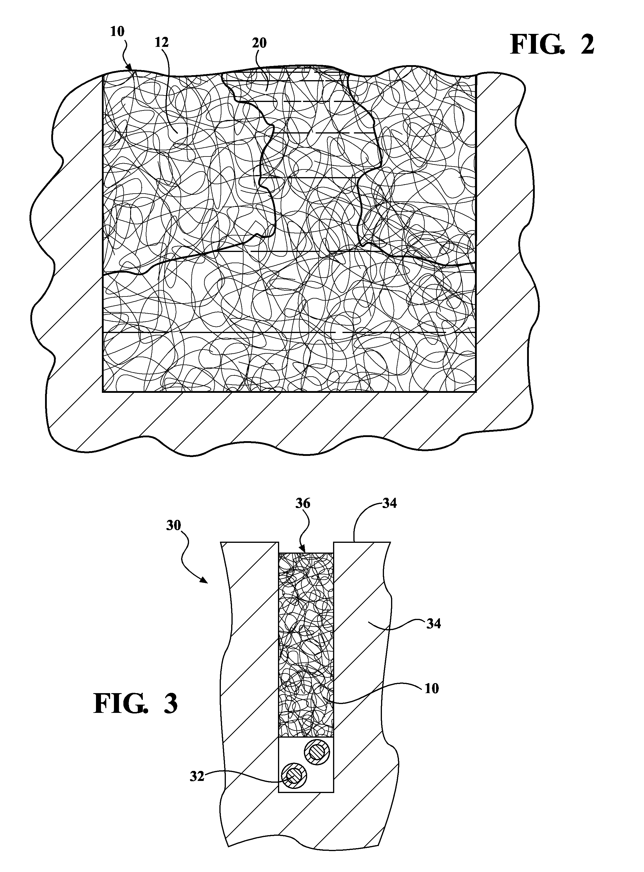
[0024]With the acceptance and explosion of micro-trenching as a process for installing fiber optics cables, efforts at developing improved micro-trenching techniques are underway. According to an aspect, the present disclosure relates to an improved system and method for micro-trenching that overcomes the problems with existing micro-trenching techniques. The aspects disclosed herein provide a micro-trench filling system and a method of filling a micro-trench.

[0025]As those o...


PUM

PropertyMeasurementUnit
Depthaaaaaaaaaa
Timeaaaaaaaaaa
Flow rateaaaaaaaaaa

Abstract

A micro-trench filling system and method of filling a trench holding a conduit is provided. The micro-trench filling system includes a trench formed into a covering surface, a conduit disposed in the bottom of the trench, a structural filler disposed on the conduit in the bottom of the trench, the structural filler made of a mesh material and having a plurality of openings; and a flowable filler poured into the trench and over the structural filler and surrounding the conduit. The flowable filler flows through the plurality of openings of the structural filler creating a bond between the flowable filler and structural filler, the flowable filler cures after a predetermined amount of time, and the structural filler and the flowable filler hold the conduit in place.

Description

RELATED APPLICATIONS[0001]This application claims benefit to provisional application No. 61 / 981,326, filed on Apr. 18, 2014 entitled Multi-Purpose Micro-Trench Insert.TECHNICAL FIELD[0002]The present disclosure broadly relates to a system and method for filling a crack or void formed through a covering substrate. More particularly, the present disclosure relates to a system and method for filling a trench formed through a covering substrate, including a structural filler disposed in the trench.BACKGROUND OF THE INVENTION[0003]Fiber optic cables have been widely employed to allow for the transmission of digital information over long distances and the need for such cables continues to grow both in the U.S. and internationally. The configuration and structure of these fiber optic cables provides better quality signal transmission than conventional cables as fiber optic cables are less likely to suffer degradation or signal loss during transmission over the cable length. However, the ex...

Claims


Application Information

Patent Timeline
IPC IPC(8): F16L1/028
CPCF16L1/028G02B6/4459G02B6/504C04B2111/70
Inventor KONCZAK, JEFFREY J.
Owner SUPERGROUT PRODS
Why Eureka
Try Eureka