Basic electromagnetic force field

a basic electromagnetic force and field technology, applied in the field of high-voltage electronics, can solve problems such as inability to summariz

Active Publication Date: 2015-10-22
MITRA MANU
View PDF5 Cites 14 Cited by
  • Summary
  • Abstract
  • Description
  • Claims
  • Application Information

AI Technical Summary

Benefits of technology

[0010]In one exemplary embodiment an electromagnetic force field is provided, which is configured to protect designated assets against projectiles, and which include three layers, a supercharged plasma window as the first layer, a curtain of high-energy laser beams as the second layer and a plurality of CNT sheets as the third layer, and wherein the laser beams are positioned at equal distance between each other and as such as to ensure that at least four laser beams are in the path of the smallest object, and wherein, the CNT layer comprises a plurality of CNT sheets. Thus, an advantage is the ability to protect designated assets, such as buildings or military tanks, from projectile weapons.

Problems solved by technology

Moreover, this Summary is not intended for use as an aid in determining the scope of the claimed subject matter.

Method used


Image

  • Basic electromagnetic force field
  • Basic electromagnetic force field
  • Basic electromagnetic force field

Examples


Embodiment Construction

[0020]What follows is a detailed description of the preferred embodiments of the invention in which the invention may be practiced. Reference will be made to the attached drawings, and the information included in the drawings is part of this detailed description. The specific preferred embodiments of the invention, which will be described herein, are presented for exemplification purposes, and not for limitation purposes. It should be understood that structural and / or logical modifications could be made by someone of ordinary skills in the art without departing from the scope of the invention. Therefore, the scope of the invention is defined by the accompanying claims and their equivalents.

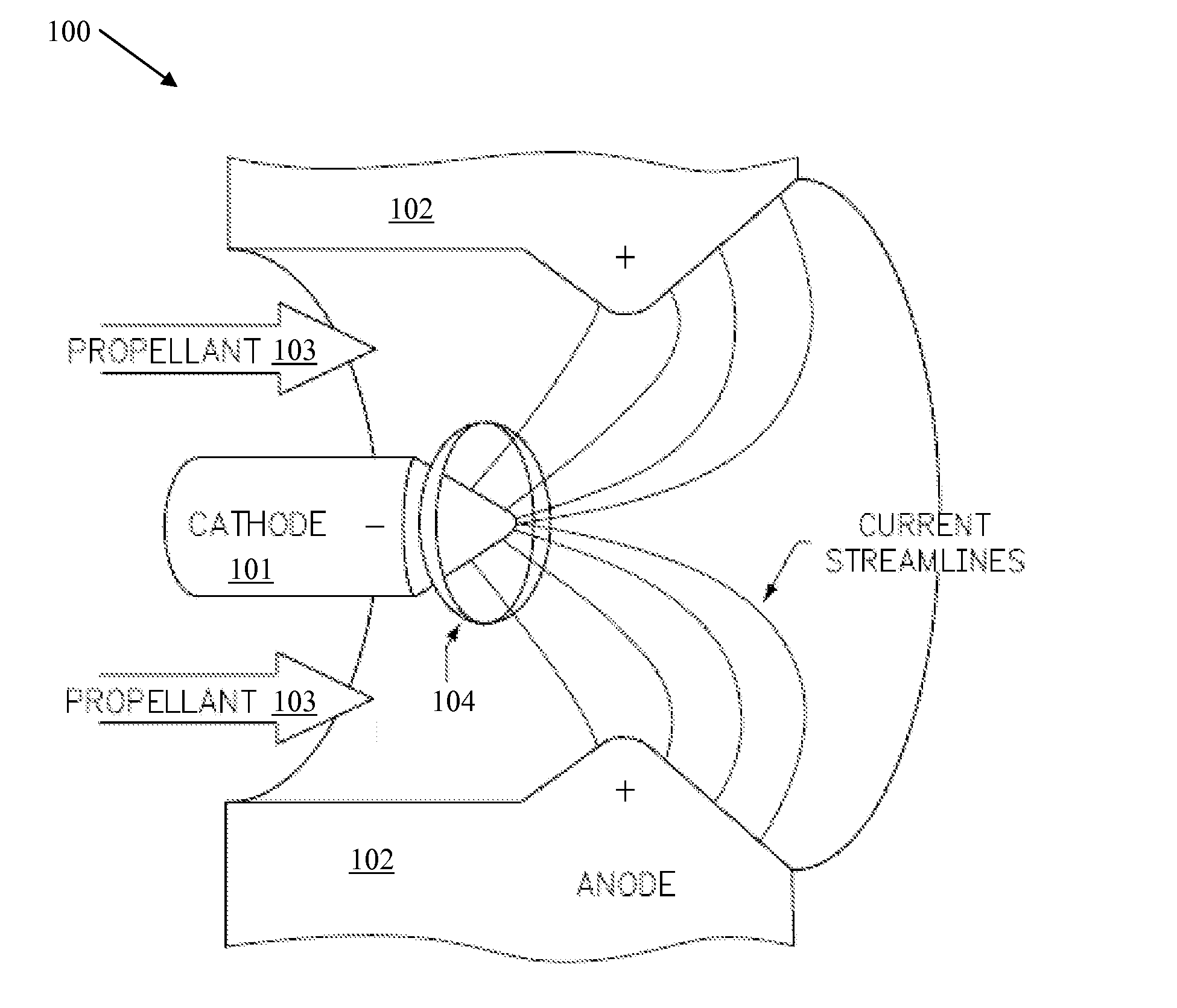
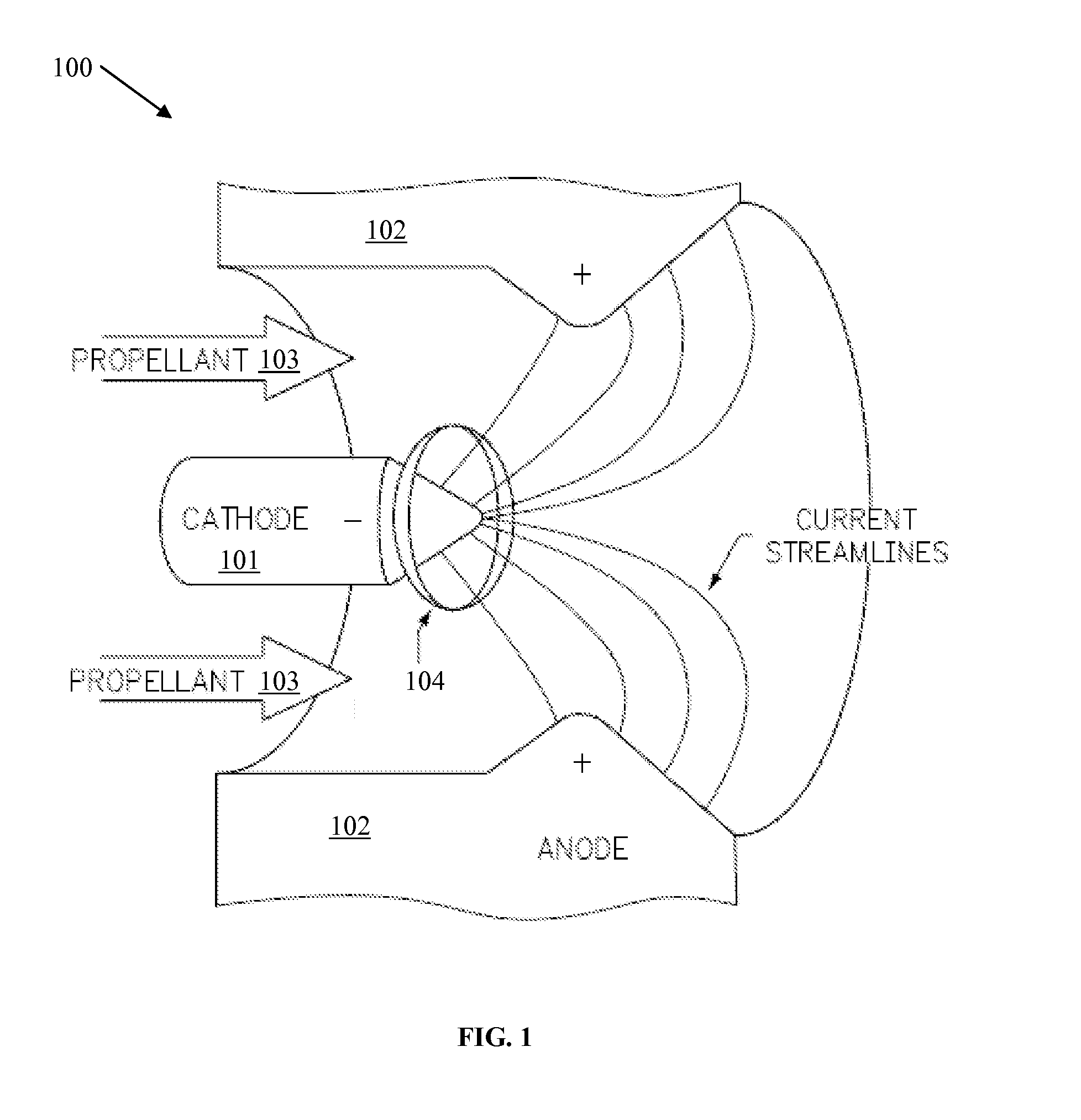
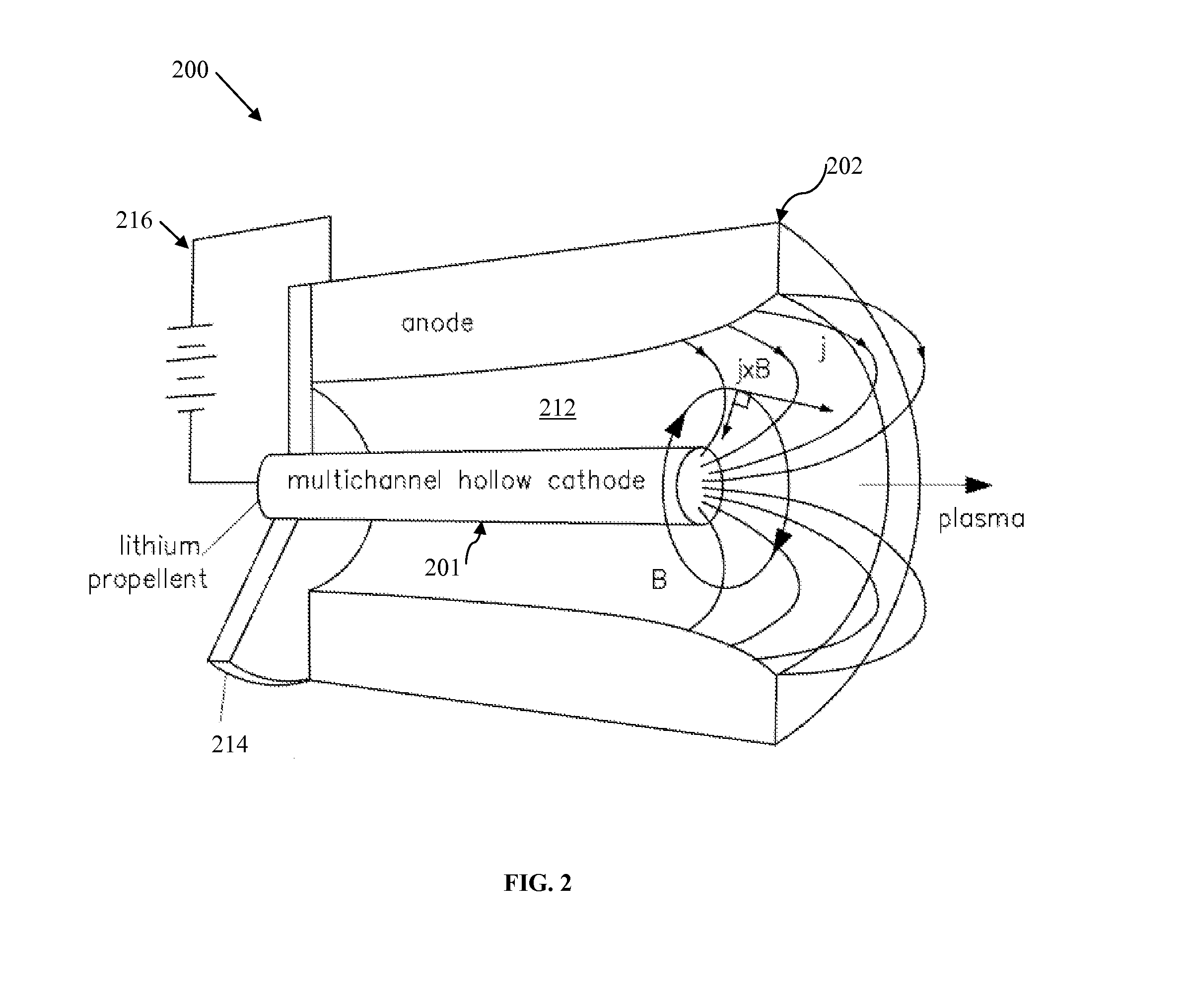
[0021]The electromagnetic force field disclosed herein, and an apparatus that incorporates it, includes a multilayered field including a first outer layer, which is a supercharged plasma window, connected to a power supply, and which is heated to temperatures high enough to vaporize metals. A seco...


PUM


Abstract

An electromagnetic force field configured to protect designated assets against incoming objects, comprising a plurality of layers, wherein the layers are a member of a group consisting of a supercharged plasma window, a curtain of high-energy laser beams arranged in a lattice-like configuration, and a carbon nanotube (CNT) layer, wherein the laser beams are positioned at equal distance between each other and as such as to ensure that at least four laser beams are in the path of the smallest object, and wherein, the CNT layer comprises a plurality of CNT sheets.

Description

CROSS-REFERENCE TO RELATED APPLICATIONS[0001]Not ApplicableSTATEMENT REGARDING FEDERALLY SPONSORED RESEARCH OR DEVELOPMENT[0002]Not ApplicableREFERENCE TO SEQUENCE LISTING, A TABLE, OR A COMPUTER PROGRAM LISTING COMPACT DISC APPENDIX[0003]Not ApplicableBACKGROUND OF THE INVENTION[0004]1. Field of the Invention[0005]The invention relates generally to the high voltage electronics and more particularly to an improved electromagnetic force field.[0006]2. Description of the Related Art[0007]It is known in the art how to generate supercharged plasma, how to contain the supercharged plasma in a plasma window, how to generate high-energy laser beams, and how to make carbon nanotubes (CNT). In the same time there is often a need to protect certain civilian assets (e.g., buildings) or military assets (e.g., tanks) from incoming objects (e.g., projectile weapons). Thus, a protective / defensive system and method is needed that will address the need for assets protection and that will employ the ...

Claims


Application Information

Patent Timeline
Patent Type & Authority Applications(United States)
IPC IPC(8): H05H1/24F03H1/00
CPCF03H1/0081H05H1/24H05H1/54H01T19/04H01T23/00H01J2201/30434F41H5/007H05H1/481
Inventor MITRA, MANU
Owner MITRA MANU
Why Eureka
Try Eureka