Vehicle air conditioning control device

a control device and vehicle technology, applied in the direction of temperatue control, process and machine control, instruments, etc., can solve the problems of power saving, shortening the service life of the substation, and temporal loss of vehicle interior comfort, so as to achieve the effect of vehicle interior comfor

Active Publication Date: 2015-10-29
MITSUBISHI ELECTRIC CORP
View PDF5 Cites 45 Cited by
  • Summary
  • Abstract
  • Description
  • Claims
  • Application Information

AI Technical Summary

Benefits of technology

[0024]The vehicle air conditioning control device according to the present invention allows the operation control for the air conditioner with consideration given not only to the vehicle interior comfort but also to the energy saving and the power saving. Thus, the vehicle air conditioning control device capable of adequate air conditioning control from the comprehensive viewpoint of the energy saving, the power saving, and the vehicle interior comfort is provided.
[0025]These and other objects, features, aspects and advantages of the present invention will become more apparent from the following detailed description of the present invention when taken in conjunction with the accompanying drawings.

Problems solved by technology

Unfortunately, there is a time lag between the detection of an increase in vehicle interior temperature and the start of the effective air conditioning, resulting in temporary loss in the vehicle interior comfort.
Thus, the stoppage of the cooler during power running levels the power consumption in the entire train, resulting in a reduction in the peak power of the substation, in other words, power saving.

Method used


Image

  • Vehicle air conditioning control device
  • Vehicle air conditioning control device
  • Vehicle air conditioning control device

Examples


embodiment 1

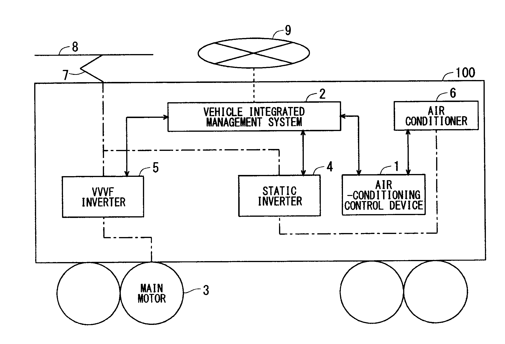
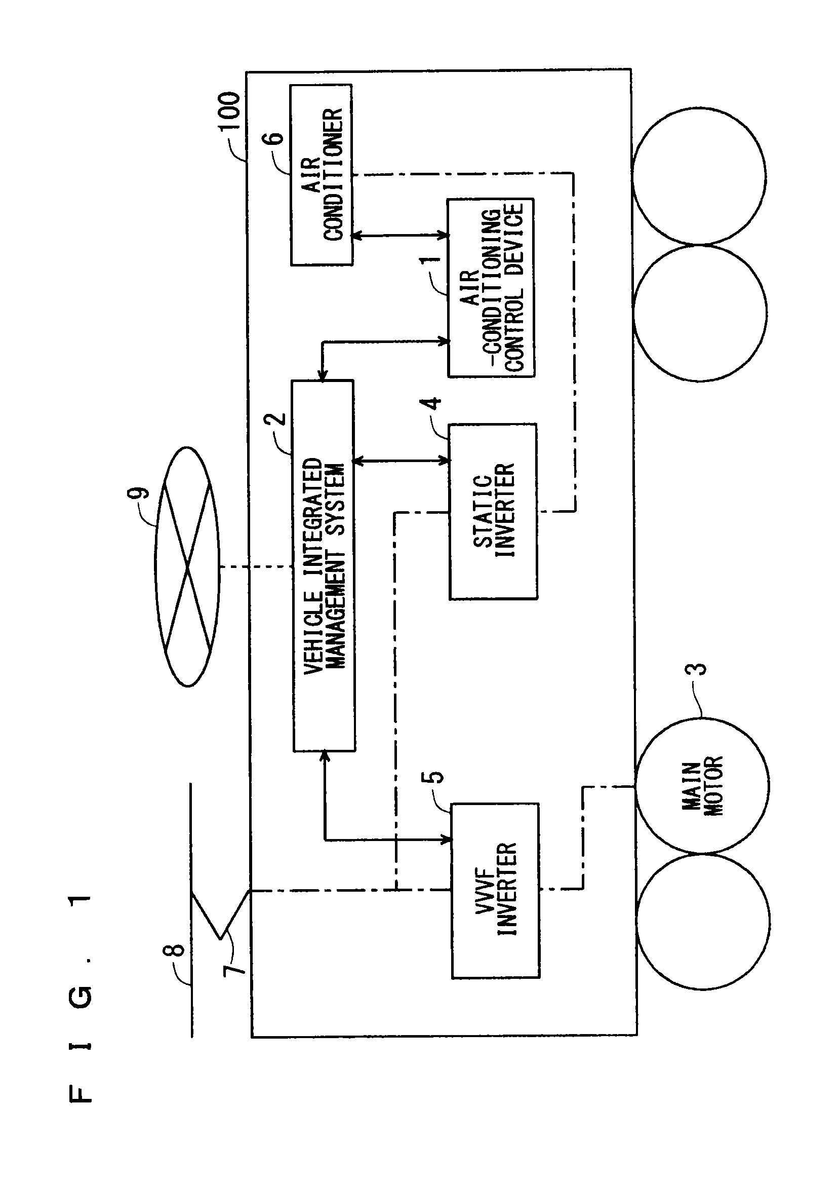
[0043]FIG. 1 is a block diagram showing a configuration of a vehicle 100 including a vehicle air conditioning control device 1 according to an embodiment 1 of the present invention. The vehicle 100 includes the vehicle air conditioning control device (hereinafter also referred to simply as “air conditioning control device”) 1, a vehicle integrated management system 2, a main motor 3, a static inverter 4, a variable voltage variable frequency (VVVF) inverter 5, an air conditioner 6, and a pantograph 7. In FIG. 1, the transmission and receipt of information is indicated by a solid arrow or a broken line and the transmission and receipt of electric power is indicated by alternate long and short dashed lines.

[0044]The vehicle integrated management system 2 integrally manages controls for the vehicle 100 including the motor control, the brake control, the door control, the air conditioning control, the lighting control, the in-train guide control, and the destination guide control. The v...

embodiment 2

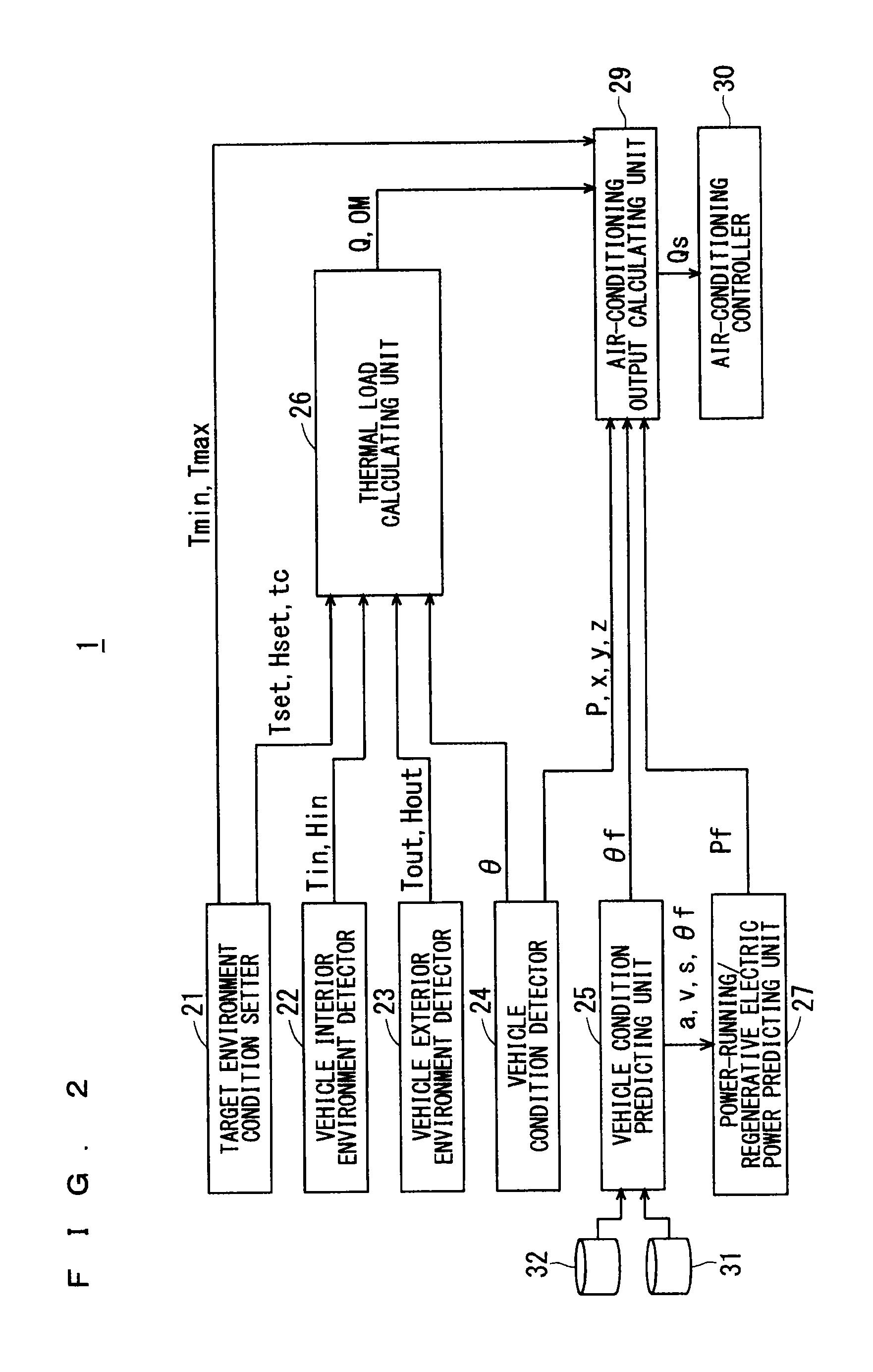
[0113]FIG. 6 is a block diagram showing a configuration of an air conditioning control device 1A according to an embodiment 2 of the present invention. As the air conditioning control device 1A according to the present embodiment, the air conditioning control device 1 according to the embodiment 1 of the present invention that is shown in FIG. 2 described above further includes a feeding voltage detector 28. Similarly to the air conditioning control device 1 according to the embodiment 1, the air conditioning control device 1A according to the present embodiment is the vehicle air conditioning control device and is included in, for example, the vehicle 100 shown in FIG. 1 described above in place of the air conditioning control device 1 according to the embodiment 1. That is, the air conditioning control device 1A, which is included in the vehicle 100, controls the air conditioner 6 in the vehicle 100.

[0114]The following describes the differences between the configuration of the air...

embodiment 3

[0129]The embodiments 1 and 2 described above have referred to the air conditioning control devices 1 and 1A capable of performing the air conditioning control, in other words, the operation control with consideration given not only to the vehicle interior comfort but also to the energy saving and the power saving. An embodiment 3 of the present invention refers to the air conditioning control device capable of creating an air conditioning operation plan including the predictions on the changes in the vehicle interior temperature and the vehicle interior humidity after the air conditioning control and of grasping, in advance, the vehicle interior comfort, the energy saving, and the power saving.

[0130]FIG. 9 is a block diagram showing a configuration of an air conditioning control device 1B according to the embodiment 3 of the present invention. Similarly to the air conditioning control devices 1 and 1A according to the embodiments 1 and 2, the air conditioning control device 1B acco...


PUM


Abstract

A vehicle air conditioning control device calculates, through a thermal load calculating unit, a vehicle interior thermal load Q on the basis of, for example, a vehicle interior temperature Tin, a vehicle interior humidity Hin, a vehicle exterior temperature Tout, a passenger load factor θ, and a vehicle-interior-temperature set value Tset. Through an air conditioning output calculating unit, the vehicle air conditioning control device calculates an output command value for an air conditioner on the basis of a vehicle-interior-temperature upper-limit value Tmax, a vehicle-interior-temperature lower-limit value Tmin, the thermal load Q, power-running/regenerative electric power P, and then, corrects the calculated output command value for the air conditioner on the basis of power-running/regenerative electric power Pf at or after a prediction time point and of a passenger load factor Of at or after the prediction time point.

Description

TECHNICAL FIELD[0001]The present invention relates to a vehicle air conditioning control device to be mounted on a vehicle to control air conditioning in the vehicle.BACKGROUND ART[0002]Various techniques have been proposed for vehicle air conditioning control devices to be mounted on vehicles of, for example, trains to control the air conditioning in the vehicle (hereinafter also described as “vehicle interior”). The traditional vehicle air conditioning control devices detect the vehicle interior temperature, the vehicle interior humidity, and the outside-air temperature and control the air conditioning capacity on the basis of the difference between the set temperature and the vehicle interior temperature, of the vehicle interior humidity, and of the outside-air temperature.[0003]When the outside-air temperature is high during, for example, summertime, a number of passengers get aboard the vehicle after the opening of the doors at the arrival in a station, and then, the vehicle in...

Claims


Application Information

Patent Timeline
Patent Type & Authority Applications(United States)
IPC IPC(8): B60H1/00
CPCB60H2001/00992B60H1/00771B60H1/00764B61D27/00G05D23/1927B60H2001/00733G05D23/1917G05D23/1931Y02T30/00
Inventor KITAMURA, SHOICHIHASHIMOTO, HIROYUKIMORI, KAZUYUKITAKAHASHI, SATORUISODA, SHOJI
Owner MITSUBISHI ELECTRIC CORP
Why Eureka
Try Eureka