Conveyor belt with zero stage splice

a conveyor belt and zero-stage technology, applied in the field of conveyor belts, can solve the problems of limiting the reliability and service life of the conveyor belt, all conveyor belts are susceptible to normal wear and tear, etc., and achieve the effects of improving spice strength, improving strength and durability, and reducing st ratings

Active Publication Date: 2015-10-29
CONTITECH TRANSPORTBANDSYSTEME GMBH
View PDF11 Cites 10 Cited by
  • Summary
  • Abstract
  • Description
  • Claims
  • Application Information

AI Technical Summary

Benefits of technology

[0006]The present invention is based upon the discovery that the steel cords in conveyor belt splices can be brazed together in a specific and cost effective manner to attain splices which having improved strength and durability. Since spices between various sections of conveyor belts are frequently the weakest area of the conveyor belt this improvement in spice strength allows for belts having lower ST ratings to be utilized to meet needed performance requirements. For instance, end-to-end splices in commercial conveyor belts currently have a dynamic splice efficiency which is typically within the range of 50% to about 55%. However, conveyor belts which are manufactures utilizing the slices of this invention exhibit a dynamic splice efficiency of greater than 75% or even 80%. In any case, the splices of this invention are stronger and more durable than those in conveyor belts which are manufactured utilizing conventional spice technology. This can accordingly lead to improvements in the service life of conveyor belts made utilizing this technology as well as improved conveyor belt reliability. By eliminating the need for multiple stage splices cost savings can also be realized.

Problems solved by technology

All conveyor belts are, of course, susceptible to normal wear and tear as well as damage from the material being transported and / or harsh environmental conditions.
However, conveyor belts splices continue to be a problem area which can limit the reliability and service life of the belt.

Method used


Image

  • Conveyor belt with zero stage splice
  • Conveyor belt with zero stage splice

Examples


Embodiment Construction

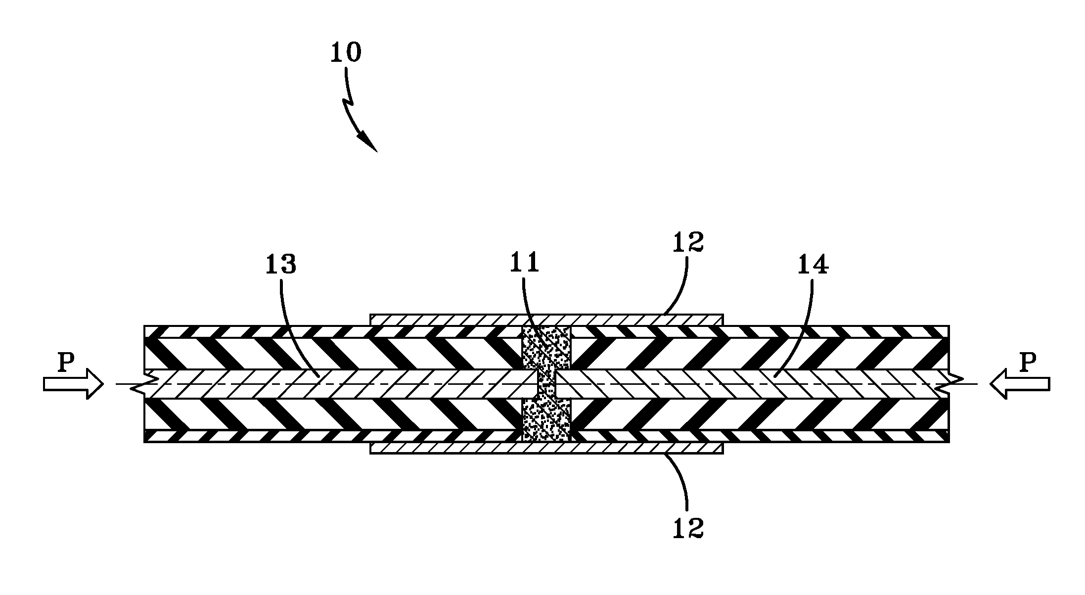
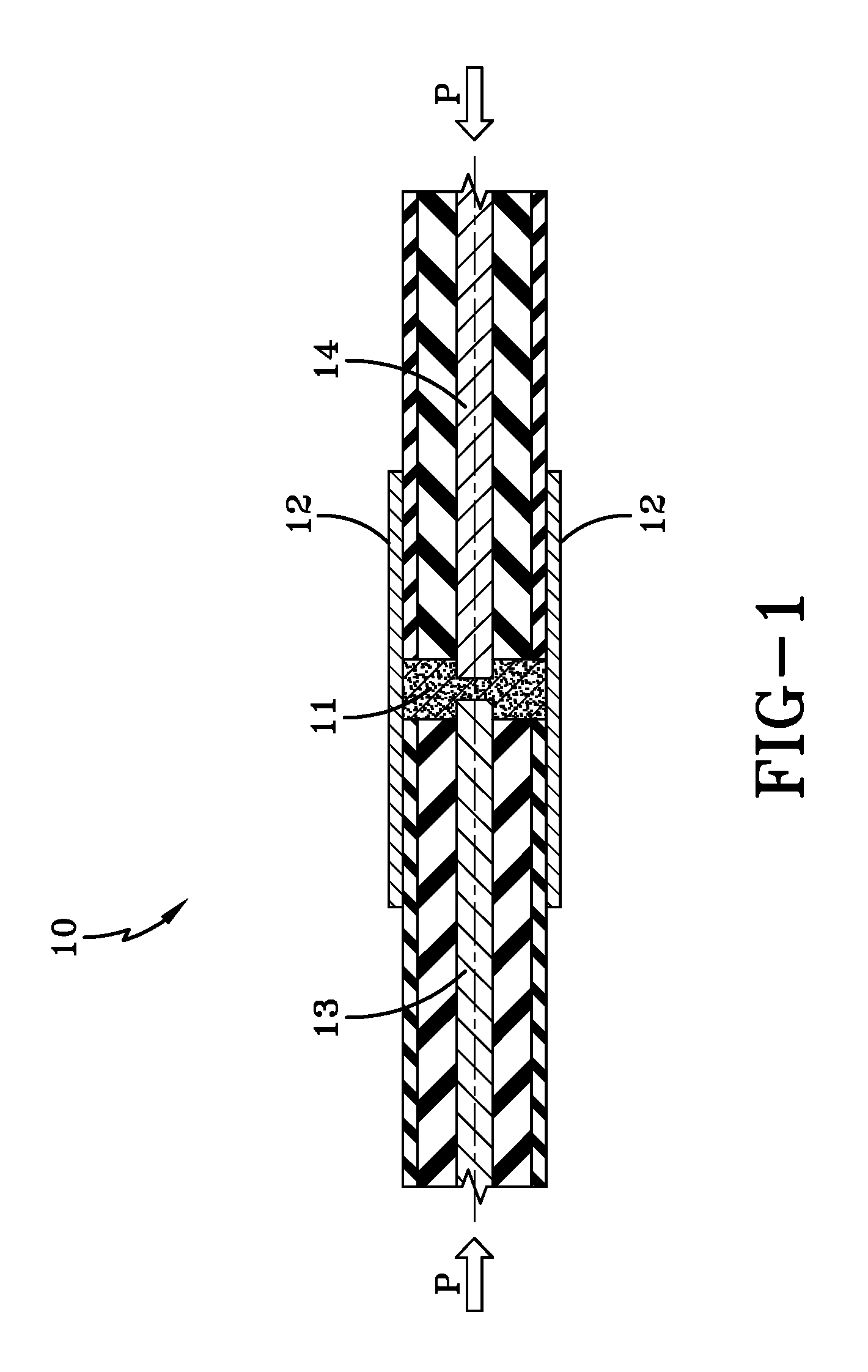
[0010]In practicing the method of this invention steel cables from joining sections (segments) of a conveyor belt are brazed together in the splices between two or more sections of the belt. The method of this invention can be employed in connecting steel cables which are comprised of virtually any type of steel and which have virtually any type of cable construction. However, in most cases it is preferable for the steel cables to be galvanized or to be brass plated.

[0011]In splicing the steel cables together a brazing alloy is inserted into a ferrule. The ferrule is typically a metal tube having a diameter which is only slightly larger than the diameter of the steel cables. The ferrule can be comprised of a wide variety of metals with steel, such as standard carbon steel or high carbon steel, typically being preferred. In some applications, utilizing a ferrule which is comprised of stainless steel is advantageous.

[0012]The braze alloy is typically comprised of at least about 70 wei...


PUM

PropertyMeasurementUnit
weight percentaaaaaaaaaa

Abstract

The present invention is based upon the discovery that the steel cords in conveyor belt splices can be brazed together in a specific and cost effective manner to attain splices which having improved strength and durability. The present invention more specifically discloses a conveyor belt which is reinforced with steel cables and which includes a first section and a second section which are bonded together with a splice, wherein said splice bonds a first set of steel cables from the first section of the conveyor belt to a second set of steel cables from the second section of the conveyor belt with a braze alloy, and wherein the first set of steel cables and the second set of steel cables are contained within a ferrule at the point of where the first set of steel cables are bonded to the second set of steel cables.

Description

[0001]The benefit of U.S. Provisional Patent Application Ser. No. 61 / 982,995, filed on Apr. 23, 2014, is claimed hereby. The teachings of U.S. Provisional Patent Application Ser. No. 61 / 982,995 are incorporated herein by reference in their entirety.FIELD OF THE INVENTION[0002]The invention relates to conveyor belts having improved splices between various sections of the belts. In these conveyor belts steel cables reinforcements are brazed together in zero stage splices.BACKGROUND OF THE INVENTION[0003]In a multitude of commercial applications, it is common to employ conveyor belts for the purpose of transporting products and materials. Such conveyor belts can serve in applications which have minimal demands, moderate demands, or in applications which are extremely demanding and which require heavy-duty conveyor belts. Conveyor belts can also very greatly in size and length. For instance, the conveyor belts used in mining applications can be very wide, for instance ten feet wide, and...

Claims


Application Information

Patent Timeline
Patent Type & Authority Applications(United States)
IPC IPC(8): B65G15/36B23K35/30C22C19/03B23K1/00
CPCB65G15/36C22C19/03B23K35/3033B23K1/0008B23K1/002B23K35/288B23K2101/32B23K1/19B29D29/06B23K2103/172B23K2101/30B23K2103/04B23K2103/16
Inventor GILG, DOUGLAS M.STEVEN, ROBIN B.WILLER, SHANNON G.MAGUIRE, DAVID J.
Owner CONTITECH TRANSPORTBANDSYSTEME GMBH
Why Eureka
Try Eureka