Built-In Exhaust Gas Maintenance Device

a maintenance device and exhaust gas technology, applied in the direction of machines/engines, charge feed systems, non-fuel substance addition to fuel, etc., can solve problems such as serious damage, and achieve the effect of a higher degree of packaging

Inactive Publication Date: 2015-10-29
BORGWARNER EMISSIONS SYST SPAIN S L U
View PDF29 Cites 13 Cited by
  • Summary
  • Abstract
  • Description
  • Claims
  • Application Information

AI Technical Summary

Benefits of technology

[0011]The present invention solves the problem of using pipes and of obtaining a higher degree of packaging by integrating the EGR heat exchanger with the catalytic converter or with the particle filter establishing a particular heat exchanger structure such that it is adapted to the large diameter of either the outlet of the catalytic converter or the outlet of the particle filter. This integration also incorporates the presence of a segment of discharge pipe as part of the exhaust line.

Problems solved by technology

One of the most intensively developing fields of technology is the EGR system technology for combustion heat engines because the recirculation of an exhaust gas requires solving various technical problems in terms of the demands imposed by the handling of a high temperature gas which contains corrosive products, which has condensate-generating possibility, and which also further contains particles that can damage sensitive engine parts.
The turbine blades are particularly sensitive and the introduction of solid particles causes serious damage in this device.
Although this configuration allows a specific degree of packaging, it involves using pipes which also occupy a large space.

Method used


Image

  • Built-In Exhaust Gas Maintenance Device
  • Built-In Exhaust Gas Maintenance Device
  • Built-In Exhaust Gas Maintenance Device

Examples


first embodiment

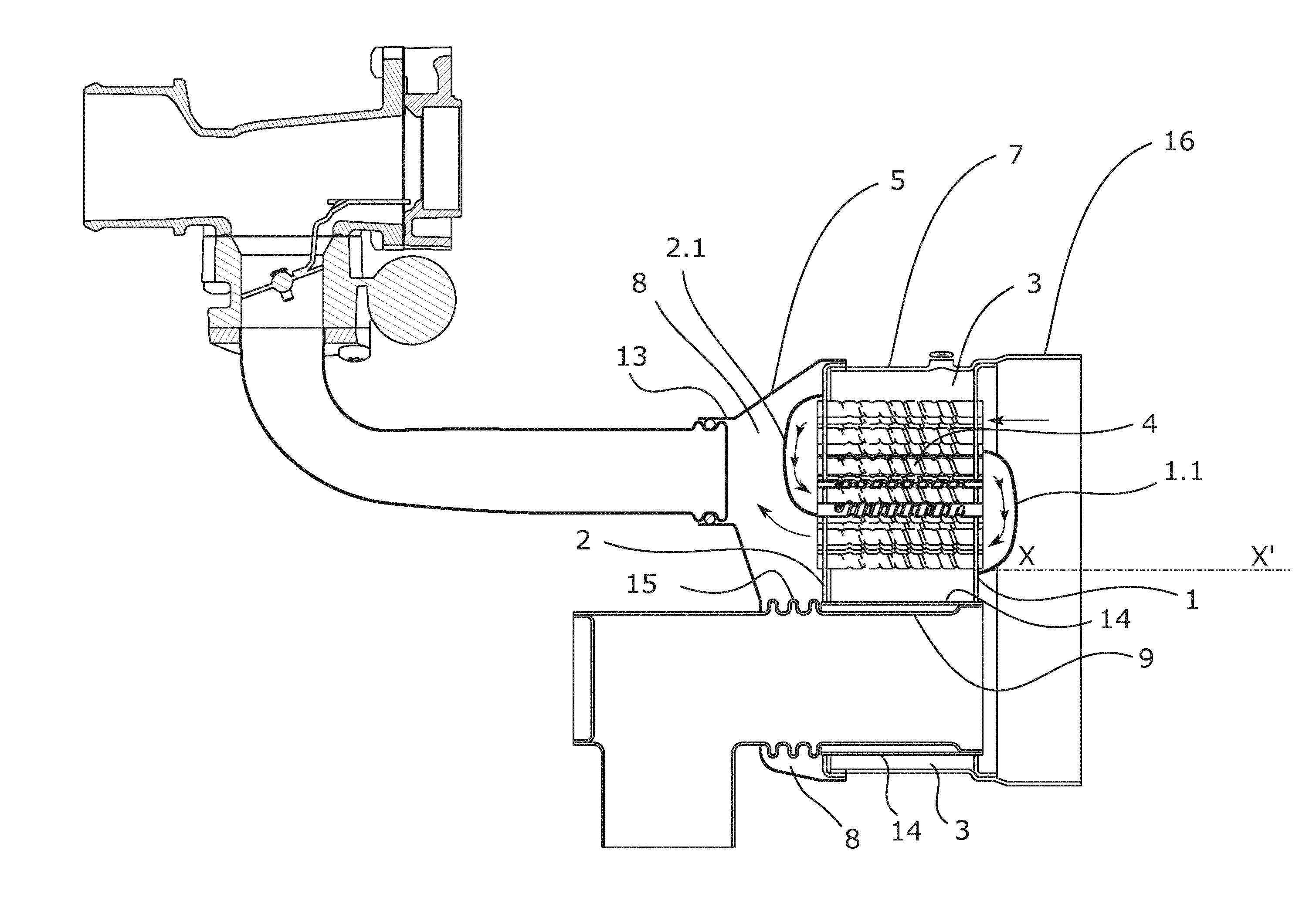
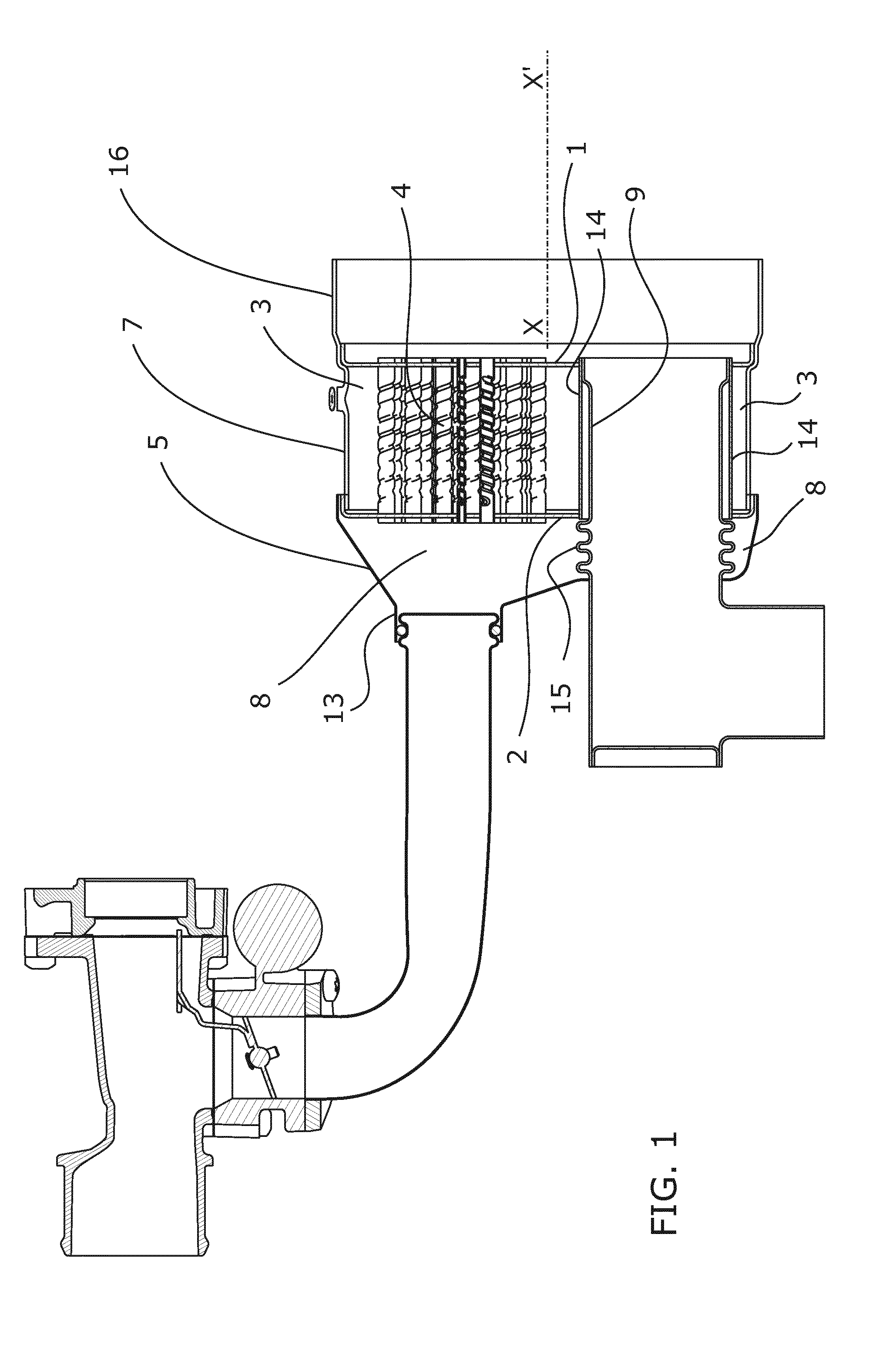
[0034]FIG. 1 schematically shows the invention. This schematic depiction corresponds to a section of the device according to a mid-plane passing through the longitudinal direction X-X′ defined by the body of the particulate filter or catalytic converter, where an EGR valve is also shown as the destination of the gas cooled by the built-in EGR heat exchanger. This figure does not show the particulate filter or catalytic converter in order to assign almost the entire graphical depiction area to the device according to the embodiment.

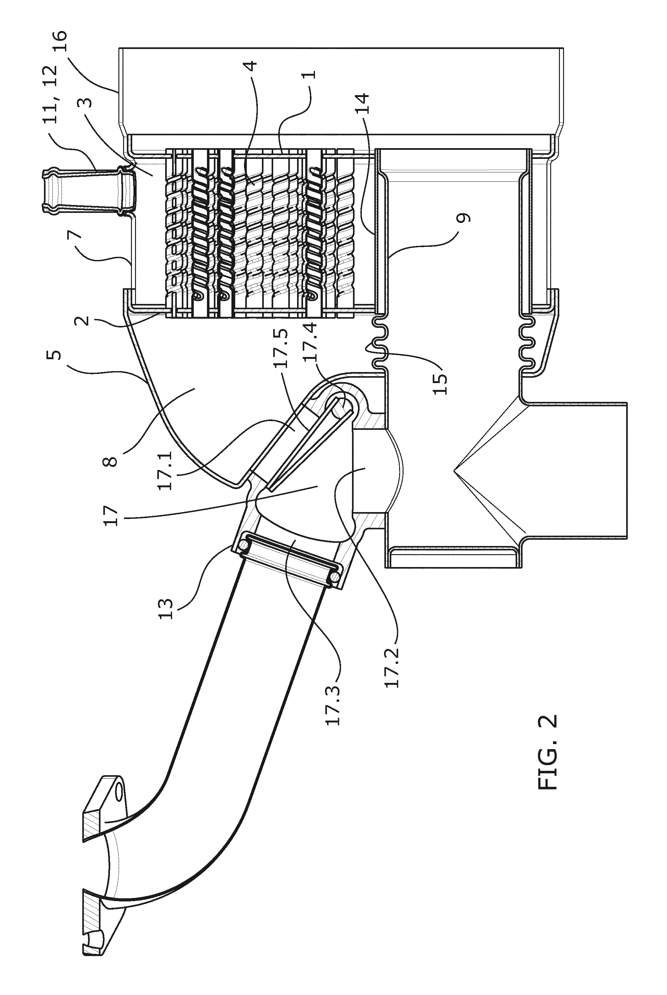
[0035]FIG. 2 shows a second embodiment with a section taken in a position and orientation similar to that used in the view of the preceding figure. In this second embodiment, the device incorporates a bypass valve.

[0036]FIG. 3 shows a third embodiment with a section taken in a position and orientation similar to that used in the view of the preceding figure. In this third embodiment, the device incorporates a valve allowing heat recovery.

[0037]FIG. 4 shows...

second embodiment

[0057]FIG. 2 shows a second embodiment comprising the same elements as the first example shown in the already described FIG. 1, and additionally comprises a bypass valve (17).

[0058]The exhaust pipe (9), prolonged outside the second casing (5), has an opening. The second casing (5) has been modified such that the cooled gas outlet (13) has an oblique exit direction directed towards the exhaust pipe (9), particularly close to the position of the opening of the exhaust pipe (9). The bypass valve (17) has a first inlet (17.1) in connection with the cooled gas outlet (13) of the second chamber (8), a second inlet (17.2) in connection with the opening of the prolongation of the segment of exhaust pipe (9); and an outlet (17.3) which is in fluid communication with the intake, for example, through an EGR valve.

[0059]The bypass valve (17) allows at least two end positions:[0060]a first position where the first inlet (17.1) is contacted with the outlet (17.3) keeping the second inlet (17.2) c...

fourth embodiment

[0090]In this fourth embodiment, it is possible to have both the bypass function and heat recovery where it is necessary to coordinate the positions of one valve (17) and the other valve (19).

[0091]The position of the valves (17, 19) corresponding to the bypass valve (17) closing the second inlet (17.2) and the second heat recovery valve (19) closing the first outlet (19.1) shows a configuration operating in the same manner as the first embodiment.

[0092]FIG. 4 shows, below the seat of the second outlet (19.2), a passage (19.6) maintaining permanent communication between both sides even though the second heat recovery valve (19) is in the end position closing the second outlet (19.2). This passage (19.6) allows the engine to keep on running even though the second heat recovery valve (19) is completely closing the second outlet (19.2) and therefore closing the exhaust. The presence of this passage (19.6) is optional since the possibility of stopping the engine by completely closing th...


PUM


Abstract

The present invention relates to a gas management device suitable for being installed at the outlet o fa particle filter or of a catalytic converter. This device is characterized by a very compact configuration having at least the heat exchanger for an EGR (Exhaust Gas Recirculation) system, particularly suitable for a low pressure system, and an exhaust gas discharge pipe which is part of the exhaust line. According to one embodiment, the device also allows integrating a bypass valve for the EGR heat exchanger. According to another embodiment, the device allows integrating a heat recovery unit participating in the EGR system. According to another embodiment, the device also allows both including a bypass and including a heat recovery unit. The degree of integration with the particle filter of the catalytic converter is maintained in all cases.

Description

OBJECT OF THE INVENTION[0001]The present invention relates to a gas management device suitable for being installed at the outlet of a particle filter or of a catalytic converter. This device is characterized by a very compact configuration having at least the heat exchanger for an EGR (Exhaust Gas Recirculation) system, particularly suitable for a low pressure system, and an exhaust gas discharge pipe which is part of the exhaust line.[0002]According to one embodiment, the device also allows integrating a bypass valve for the EGR heat exchanger. According to another embodiment, the device allows integrating a heat recovery unit participating in the EGR system. According to another embodiment, the device also allows both including a bypass and including a heat recovery unit. The degree of integration with the particle filter of the catalytic converter is maintained in all cases.BACKGROUND OF THE INVENTION[0003]One of the most intensively developing fields of technology is the EGR sys...

Claims


Application Information

Patent Timeline
Patent Type & Authority Applications(United States)
IPC IPC(8): F02M25/07
CPCF02M25/0734
Inventor CASTANO GONZALEZ, CARLOS MANUELCIVEIRA DOMINGUEZ, SONIA
Owner BORGWARNER EMISSIONS SYST SPAIN S L U
Why Eureka
Try Eureka