
Carbon material and a process for its manufacture

a carbon material and process technology, applied in the field of carbon materials, can solve the problems of excessive surface coating of carbonaceous materials, insufficient compression excessive particle strength of negative electrode materials, so as to improve charge and discharge efficiency and cycle life, the effect of increasing density

Inactive Publication Date: 2013-03-12
NIPPON DENKO CO LTD
View PDF11 Cites 0 Cited by
  • Summary
  • Abstract
  • Description
  • Claims
  • Application Information

AI Technical Summary

Benefits of technology

The carbon material achieves enhanced electrode density and capacity with improved charge and discharge efficiency and cycling performance, while minimizing electrolyte decomposition and maintaining moderate particle strength, thus overcoming the limitations of previous surface coating methods.

Problems solved by technology

In our research, we found that when a core is made of graphite powder and its surface is coated with a carbonaceous material in an amount such that physical properties such as a specific Raman spectrum appears, the amount of surface coating by the carbonaceous material becomes excessive, and the particle strength of a negative electrode material becomes too high.
As a result, the negative electrode material cannot be adequately compressed and the electrode density does not increase.
If the material is excessively compressed so as to obtain a high electrode density, the surface coating is excessively crushed, and an even larger decrease in the charge and discharge efficiency and an even greater worsening of cycling performance occurs.
Accordingly, the primary cause of a decrease in charge and discharge efficiency due to decomposition of an electrolytic solution is thought to be decomposition of the solution which occurs at the surface and particularly on the edge planes of graphite particles.

Method used


Image

  • Carbon material and a process for its manufacture
  • Carbon material and a process for its manufacture

Examples


example 1

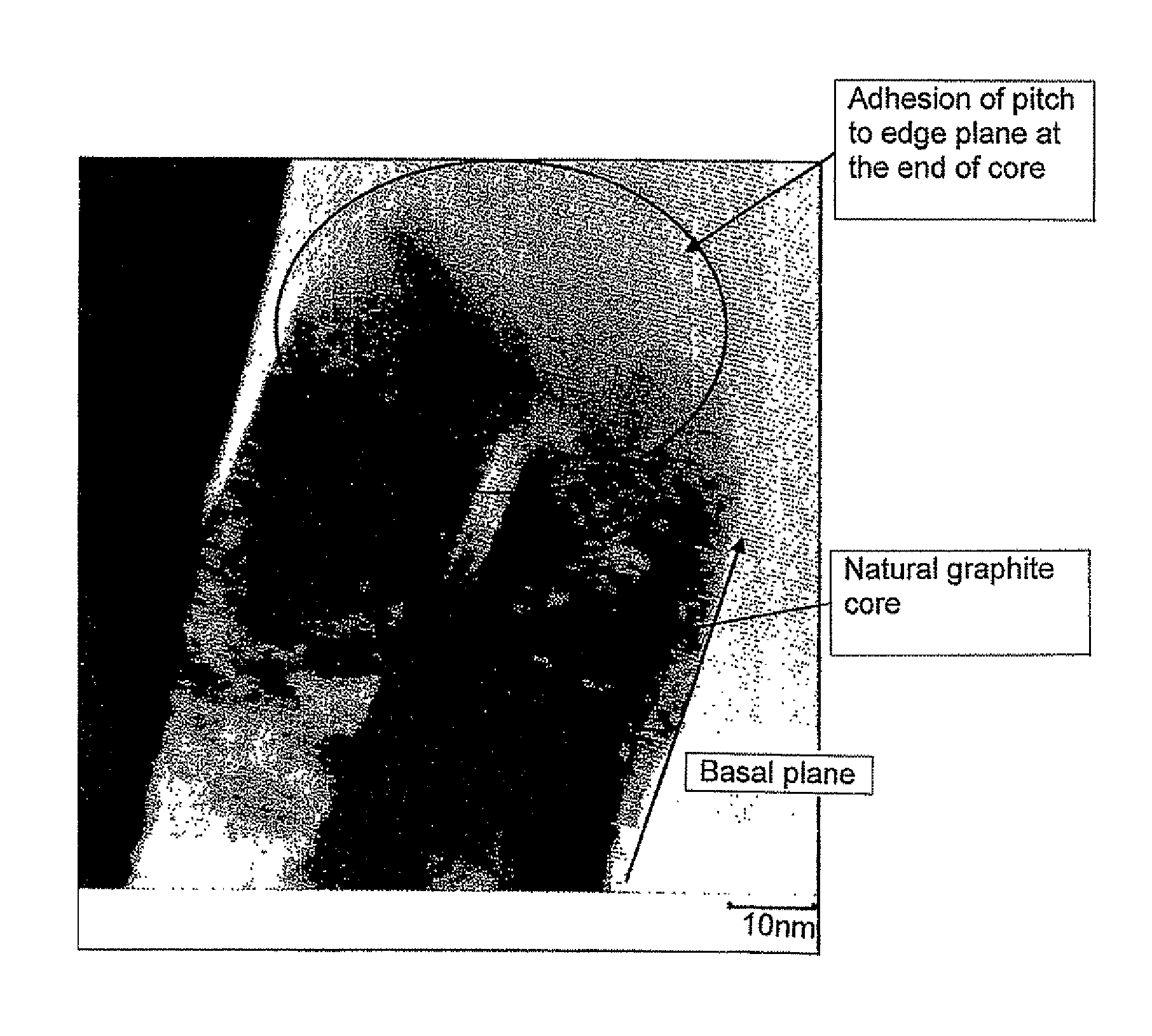
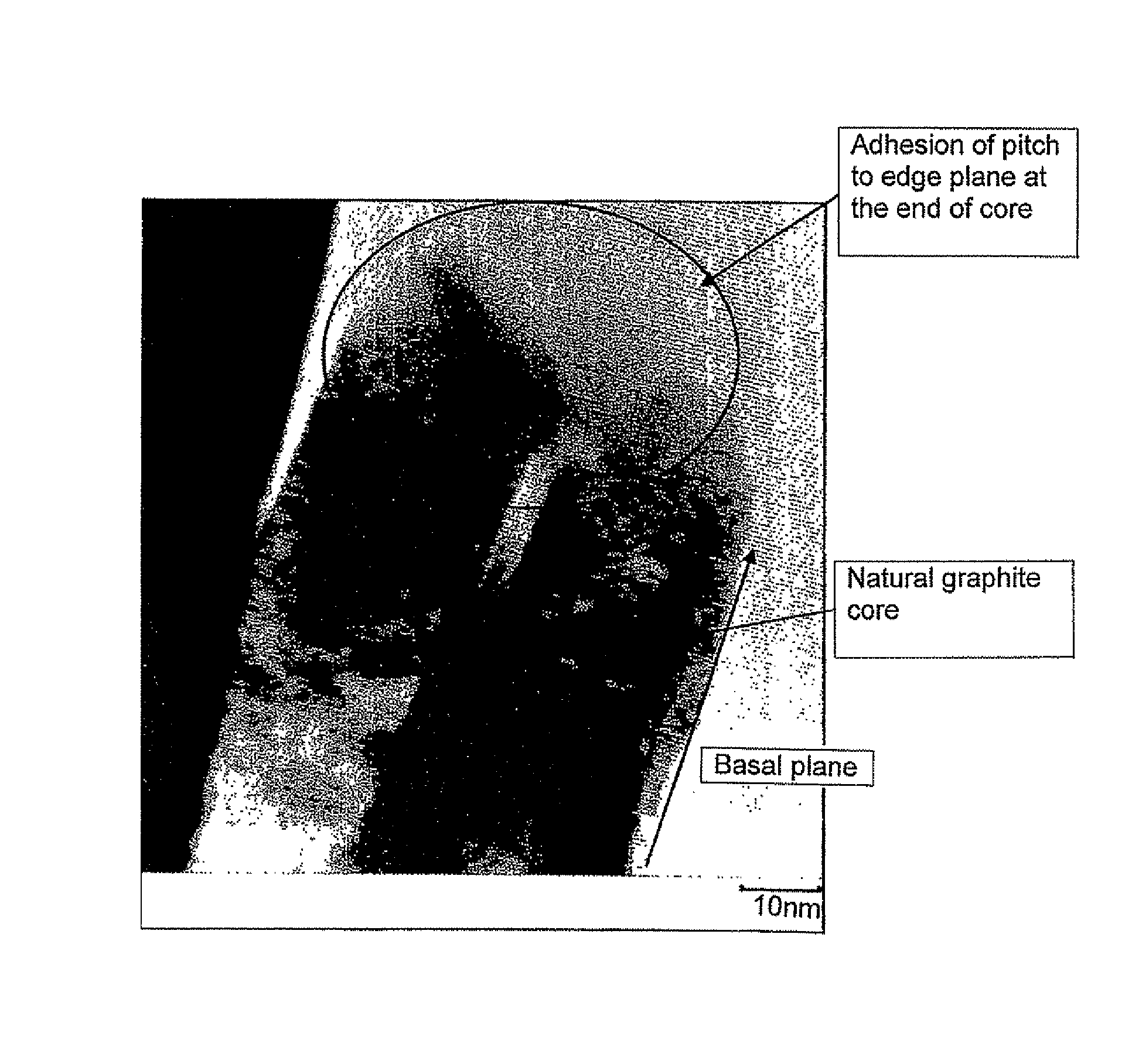
[0070]95.5 parts of natural graphite powder which had undergone spheroidizing treatment and which had an average particle diameter of 19 μm and a specific surface area (S1) of 5.5 m2 / g and 4.5 parts of coal-derived pitch powder having an average particle diameter of 50 μm and a softening point of 85° C. were mixed in solid state using a V blender.

[0071]The resulting mixed powder was placed into a heating furnace, in which the powder is subjected to heat treatment in a nitrogen atmosphere at 1000° C. for 1 hour and then allowed to cool to obtain a carbon material in which low temperature calcined carbon formed by carbonization of pitch adhered to the surface of graphite powder. Sticking of the graphite powder particles to each other did not take place. The average particle diameter and the specific surface area (S2) of the resulting carbon material were measured.


PUM

PropertyMeasurementUnit
temperatureaaaaaaaaaa
particle diameteraaaaaaaaaa
specific surface area S2aaaaaaaaaa

Abstract

A carbon material suitable as a negative electrode material for a lithium ion battery which can suppress decomposition of a nonaqueous electrolytic solution, which has excellent compressibility capable of highly dense packing, and which can form an electrode of high capacity without worsening charge and discharge efficiency or cycling performance. Graphite powder A having an average particle diameter of 10-30 μm and a specific surface area S1 of at most 12.5 m2 / g and pitch powder B having a softening point of 80-180° C. and an average particle diameter of 15-150 μm are mixed in proportions such that the mass ratio A / B is 98 / 2-95.5 / 4.5, and the resulting mixed powder is subjected to heat treatment in a stationary condition in an inert atmosphere at 900-1100° C. to carbonize the pitch and thereby manufacture a carbon material having carbon adhered to the surface of the above-described graphite powder. Carbon preferentially adheres to the edge planes of the graphite particles. The carbon material has a specific surface area S2 of 1.0-5.0 m2 / g, and it satisfies 0.4≦S2 / S1≦0.8.

Description

[0001]This application is a continuation of International Patent Application No. PCT / JP2008 / 051391, filed Jan. 30, 2008. This PCT application was not in English as published under PCT Article 21(2).TECHNICAL FIELD[0002]This invention relates to a carbon material suitable for a negative electrode of a nonaqueous secondary battery such as a lithium ion (secondary) battery and to a process for its manufacture.BACKGROUND ART[0003]Carbon materials which constitute negative electrodes of lithium ion secondary batteries have primarily been graphite materials and particularly artificial graphite powder.[0004]There has been much research concerning how to increase the capacity per unit mass of graphite materials used for negative electrodes in order to increase the capacity of lithium ion batteries. As a result of such efforts, a graphite material has been developed which gives a capacity exceeding 360 mAh / g, which is close to the theoretical capacity of 372 mAh / g of graphite. Accordingly, i...

Claims


Application Information

Patent Timeline
Patent Type & Authority Patents(United States)
IPC IPC(8): H01M4/02H01M4/58H01M4/587H01M10/0525H01M10/36
CPCC01B31/02H01M4/587H01M10/4235H01M4/362C01P2004/61C01P2006/12H01M4/02H01M2004/021H01M10/0525C01B32/05Y02E60/10
Inventor FUJIWARA, TOORUYAMAMOTO, HIROSHI
Owner NIPPON DENKO CO LTD
Learn More