
Gas insulated switchgear monitoring apparatus and method

Active Publication Date: 2015-10-29
MODTECH
View PDF4 Cites 26 Cited by
  • Summary
  • Abstract
  • Description
  • Claims
  • Application Information

AI Technical Summary

Benefits of technology

The patent is about a device that can estimate gas density accurately during slow leaks or fill times. This is done by using processors that are distributed throughout the device and connected by a network. The device also has a user interface to easily communicate with the user.

Problems solved by technology

A decline in gas level due to gas leakage or other losses must be detected and maintenance activities must be scheduled to restore gas levels or else unsafe conditions or catastrophic equipment failure may result.
These density monitors typically provide a second level of alarm when gas levels become so low that safe operation of the switchgear is not possible.
Unfortunately, they do not provide the information needed to enable operators to fine tune maintenance and repair schedules and minimize associated operating costs.
Further, the environmental cost of gases leaked from such switchgear can be severe.
The two-level density monitor type products are lacking when it comes to early detection and mitigation of environmentally harmful gas leaks.
It is well known that real world gases behave in a way that is more or less non-ideal as the density and temperature of the gas varies.
Localized heating of gas near conductors and contacts carrying variable electrical currents within the tank of electrical equipment is another source of temperature disequilibrium.
In the example above, the temperature discrepancies, if unaccounted, lead to density estimate errors ranging from −1.62 to +0.90 kg / m3.
Given that the typical operating densities for switchgear charged with SF6 are in the 40 kg / m3 range, the inaccuracy represents a significant percentage error.

Method used


Image

  • Gas insulated switchgear monitoring apparatus and method
  • Gas insulated switchgear monitoring apparatus and method
  • Gas insulated switchgear monitoring apparatus and method

Examples


Embodiment Construction

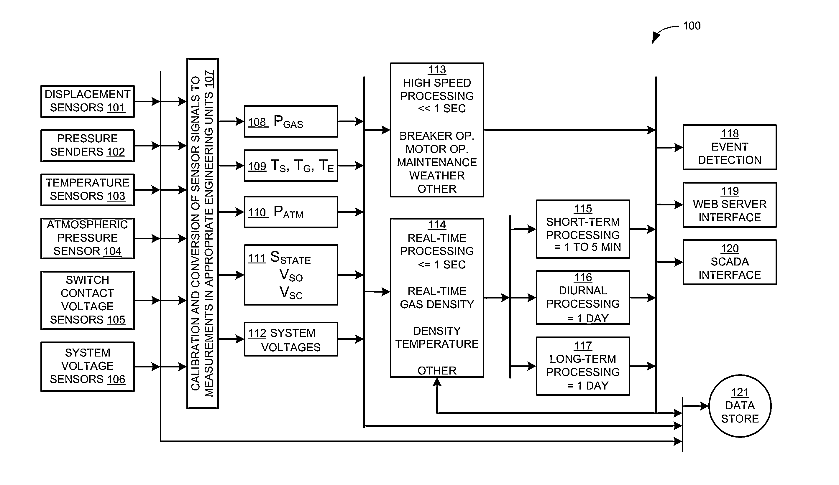
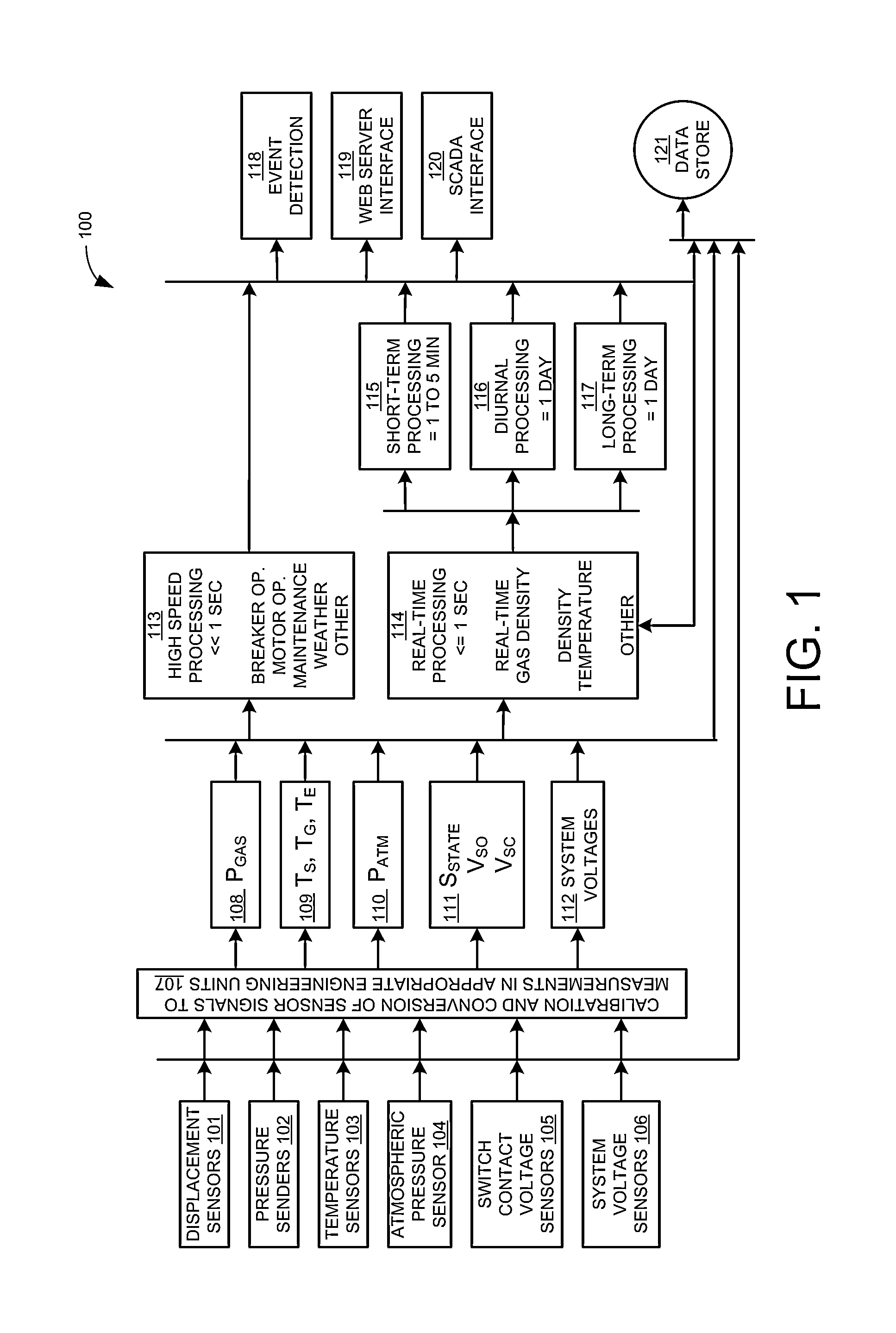
[0071]FIG. 1 is a high level block diagram 100 of the signal processing performed in the present invention.

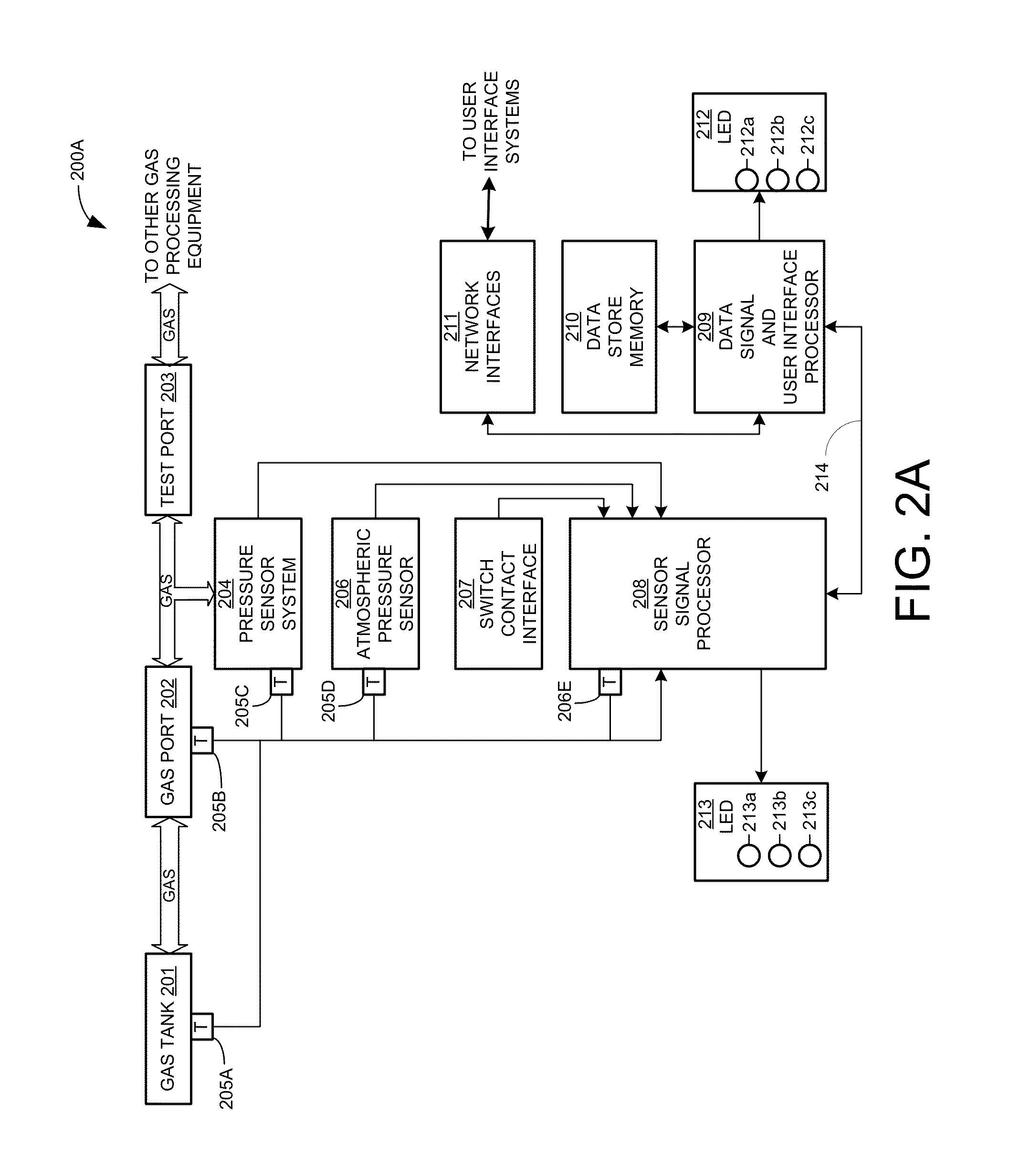
[0072]FIG. 2A is a high level block diagram 200A of the apparatus of the present invention monitoring gas density in tank 201. One or more external temperature sensors 205A may be applied directly to the tank. Gas in tank 201 is connected to the apparatus at gas port 202 using flexible or rigid tubing material. Temperature may be measured at or near 202 using temperature sensor 205B. Gas is conveyed from the gas port to pressure sensor 204.

[0073]The pressure sensor(s) may be of any type. In one embodiment, the pressure sensor is constructed of a moveable mechanical member that moves in response to gas pressure changes. In this embodiment, the controller operates one or more position sensors providing real-time information about the displacement of the mechanical member that in turn can be processed using specific algorithms to reveal the gas pressure. The pressure indicated is ...


PUM


Abstract

Mechanical, electronic, algorithmic, and computer network facets are combined to create a highly integrated advanced sensor that monitors the gas density, state-of-repair, and events associated with switchgear. Measurements of gas pressure, atmospheric pressure, gas temperature, are used with models of the non-ideal behavior of a particular gas to realistically estimate gas density. A hierarchical system of signal processing optimizes measurements working within high-frequency, real-time, short-term, medium-term, diurnal, long-term, and historical timeframes and overcomes measurement errors present in real-world applications. The time at which a condition such as gas density will reach a particular level is calculated. Events such as threshold attainments and switchgear operation are detected. A large memory stores all raw data values allowing flexible re-processing and verification at any future time. Instantaneous as well as logged information is communicated in convenient formats over a selected digital network. An embedded web server provides a familiar graphical user interface.

Description

[0001]This application claims priority to, and the benefit of copending U.S. Provisional patent application Ser. No. 61 / 986088 filed Apr. 29, 2014 which is incorporated herein by reference hereto in its entirety. The application claims priority to, and the benefit of copending U.S. Provisional patent application Ser. No. 62 / 103958 filed Jan. 15, 2015 which is incorporated herein by reference hereto in its entirety.FIELD OF THE INVENTION[0002]The field of invention is the field of intelligent gas sensors with the capability to effectively measure the pressure and temperature of gas contained in a fixed volume, to estimate the gas density, and to track changes in density that occur as a result of additions or losses of gas. The invention is also in the field of intelligent, networked sensors that exchange sensor measurements and sensor configuration and control information over communication networks. The field of invention also includes sensors that measure time-varying environmental...

Claims


Application Information

Patent Timeline
IPC IPC(8): G01N9/26G01N33/00
CPCG01N33/0006G01N9/266H02B13/065H02B13/0655
Inventor SCHEUCHER, KARL FREDERICK
Owner MODTECH
Learn More