Overcurrent detection circuit

a detection circuit and overcurrent technology, applied in the field of overcurrent detection circuits, can solve the problems of difficult detection of overcurrent flowing through the switching element on the high side accurately and stably, and achieve the effects of simple detection, accurate and stably detection, and high accuracy

Active Publication Date: 2015-10-29
FUJI ELECTRIC CO LTD
View PDF4 Cites 22 Cited by
  • Summary
  • Abstract
  • Description
  • Claims
  • Application Information

AI Technical Summary

Benefits of technology

[0017]In the overcurrent detection circuit having the above mentioned configuration, the reference voltage generation circuit itself generates reference voltage having a predetermined temperature characteristic, that is, a temperature characteristic corresponding to the output temperature characteristic of the current detection element. Therefore according to the overcurrent detection circuit having this configuration, overcurrent flowing through the switching element can be detected simply, accurately and stably. As a result, the switching element can be protected from overcurrent flowing through the switching element with certainty.
[0018]Particularly in the overcurrent detection circuit according to the present invention, the reference voltage is generated, via the instrumentation amplifier, from the differential voltage between the divided voltage of the standard voltage by the first resistance voltage dividing circuit using two types of resistors having different temperature characteristics, and the divided voltage of the standard voltage by the second resistance voltage dividing circuit using resistors having same temperature characteristics. Therefore the reference voltage can be stably generated without causing problems if a conventional bipolar transistor is used for generation. As a result, overcurrent flowing through the switching element can be detected stably and highly accurately, with a simple configuration, which has significant effects in practical terms.

Problems solved by technology

However, the following problems occur in the case where the overcurrent detection circuit, having the configuration shown in FIG. 7, is integrated into the driver circuit on the high side in the drive control circuit, which turns the first and second switching elements respectively ON.
This means that it is difficult to detect overcurrent flowing through the switching element on the high side accurately and stably.

Method used


Image

  • Overcurrent detection circuit
  • Overcurrent detection circuit
  • Overcurrent detection circuit

Examples


Embodiment Construction

[0026]An overcurrent detection circuit according to an embodiment of the present invention will be described with reference to the drawings.

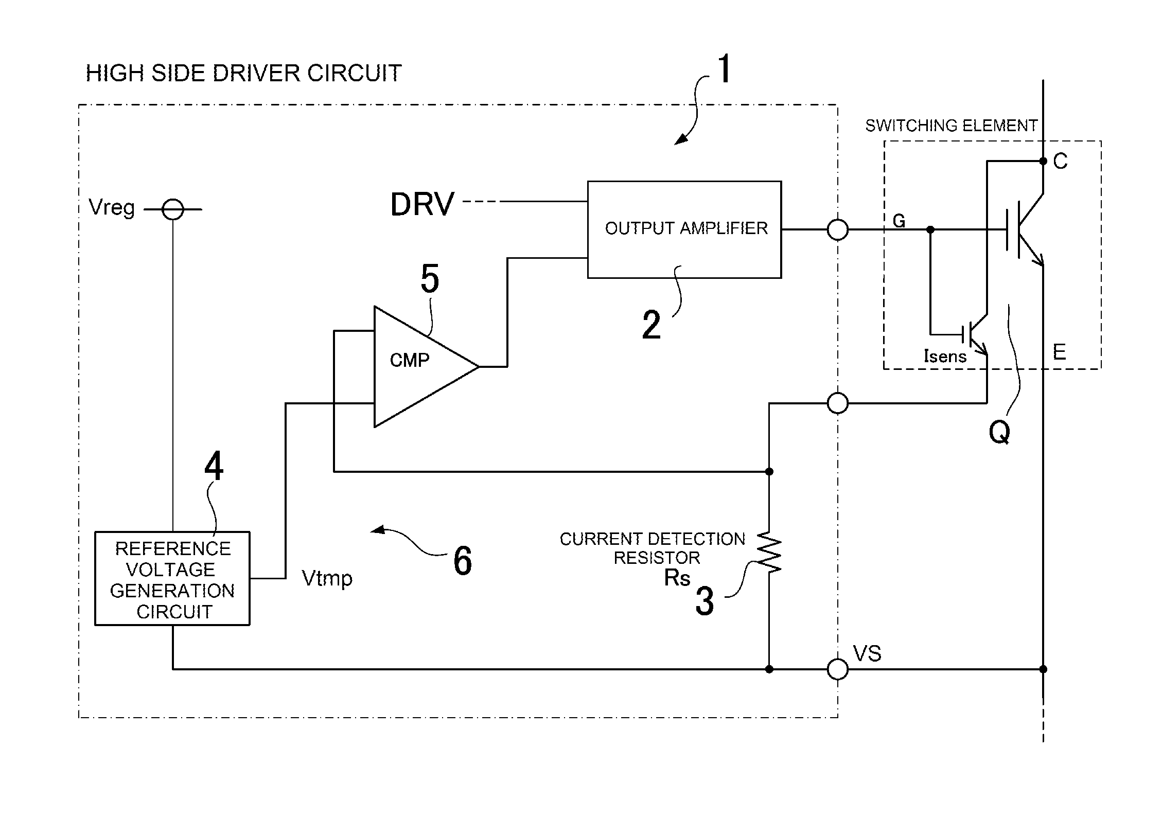
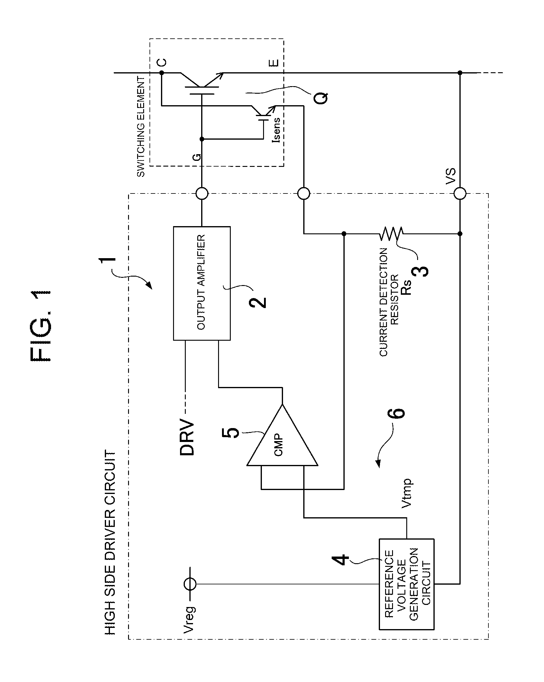
[0027]FIG. 1 shows the general configuration of a key section of a driver circuit that turns the switching element Q on a high side ON / OFF, constituting a half bridge circuit of a power convertor. The switching element Q is constituted by an IGBT having a high withstand voltage, and a current sensing IGBT is integrated with this IGBT by mirror-connection. The current sensing IGBT outputs a micro-current in proportion to the current flowing through the IGBT.

[0028]The driver circuit 1 that turns the switching element Q ON / OFF is mainly constituted by an output amplifier 2, to which a drive control signal DRV is inputted and which applies a predetermined drive pulse signal to a gate of the switching element Q. The driver circuit 1 also includes a current detection resistor 3 that generates voltage in proportion to current flowing through the switch...


PUM


Abstract

An overcurrent detection circuit includes a current detection resistor that generates a voltage in proportion to current flowing through a switching element and a comparator that compares the voltage detected via the current detection resistor and a reference voltage generated by a reference voltage generation circuit to thereby detect overcurrent flowing through the switching element. In particular, the reference voltage generation circuit includes: a first resistance voltage dividing circuit that resistance-divides a standard voltage by connecting, in series, two types of resistors having different temperature characteristics; a second resistance voltage dividing circuit that resistance-divides the standard voltage by connecting, in series, resistors having the same temperature characteristics; and an instrumentation amplifier that generates the reference voltage according to the difference between the divided output voltages of the first and second resistance voltage dividing circuits.

Description

CROSS-REFERENCE TO RELATED APPLICATIONS[0001]This application is a bypass continuation application of International Application number PCT / JP2014 / 063914, filed on May 27, 2014 and designating the United States. Furthermore, this application claims the benefit of priority of Japanese Patent Application No. 2013-123180, filed on Jun. 11, 2013. The disclosures of both of these earlier applications are incorporated herein by reference.TECHNICAL FIELD[0002]The present invention relates to an overcurrent detection circuit having a simple configuration that can accurately detect overcurrent flowing through a switching element of a power convertor.BACKGROUND ART[0003]In a power supply device for driving an AC load, such as a motor or a power convertor, a half bridge circuit created by directly connecting first and second switching elements can be employed. This power convertor switches the input DC power via the first and second switching elements, and supplies AC power to the load, which i...

Claims


Application Information

Patent Timeline
Patent Type & Authority Applications(United States)
IPC IPC(8): G01R19/165H02H3/08H02H1/00
CPCG01R19/16547H02H1/0007H02H3/087H02H6/00H02M3/33507H02H3/08H02M1/08H02M1/32H03K17/0828H03K17/14H03K2217/0027H02M1/0009
Inventor AKAHANE, MASASHI
Owner FUJI ELECTRIC CO LTD
Why Eureka
Try Eureka