Automated method and apparatus for testing a crowbar circuit of a power converter

a technology of power converter and automatic method, which is applied in the direction of power supply testing, electronic protection circuit testing, instruments, etc., can solve the problems of time-consuming and expensive, and certain power converters may have complex systems built around a certain topology

Active Publication Date: 2015-10-29
GENERAL ELECTRIC CO
View PDF10 Cites 20 Cited by
  • Summary
  • Abstract
  • Description
  • Claims
  • Application Information

AI Technical Summary

Benefits of technology

[0007]In one aspect, the present subject matter is directed to a method for testing a crowbar circuit of a power converter with an existing power conversion assembly of a renewable energy system. The method includes implementing a first test sequence for testing operability of an anti-parallel diode of the crowbar circuit. Another step includes determining a first current-voltage feedback of the power converter based on the first test sequence, wherein the first current-voltage feedback is

Problems solved by technology

Certain power converters, however, may have complex systems built around a certain topology, e.g. a DC-DC power converter.
In addi

Method used


Image

  • Automated method and apparatus for testing a crowbar circuit of a power converter
  • Automated method and apparatus for testing a crowbar circuit of a power converter
  • Automated method and apparatus for testing a crowbar circuit of a power converter

Examples


Embodiment Construction

[0022]Reference now will be made in detail to embodiments of the invention, one or more examples of which are illustrated in the drawings. Each example is provided by way of explanation of the invention, not limitation of the invention. In fact, it will be apparent to those skilled in the art that various modifications and variations can be made in the present invention without departing from the scope or spirit of the invention. For instance, features illustrated or described as part of one embodiment can be used with another embodiment to yield a still further embodiment. Thus, it is intended that the present invention covers such modifications and variations as come within the scope of the appended claims and their equivalents.

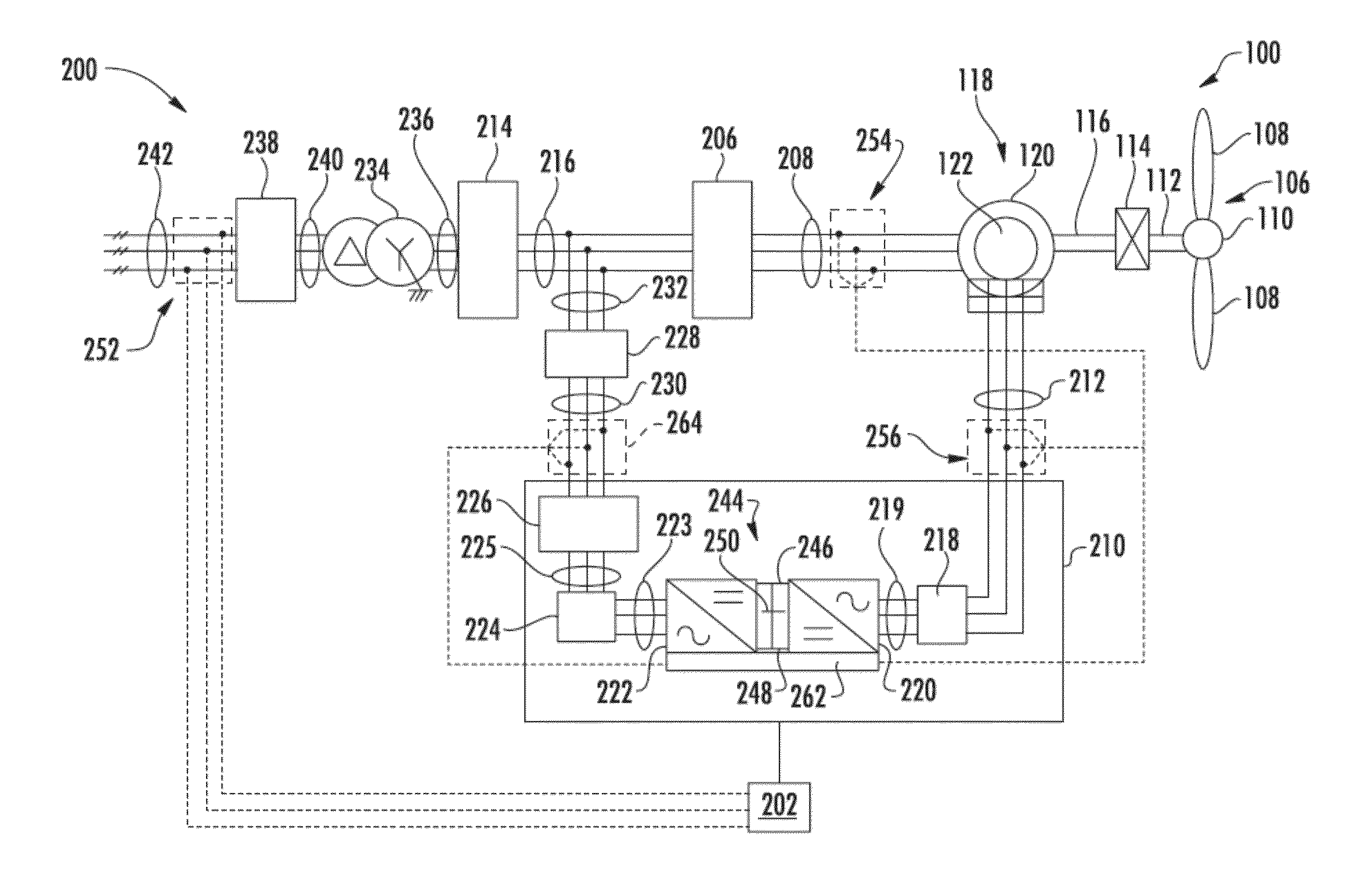
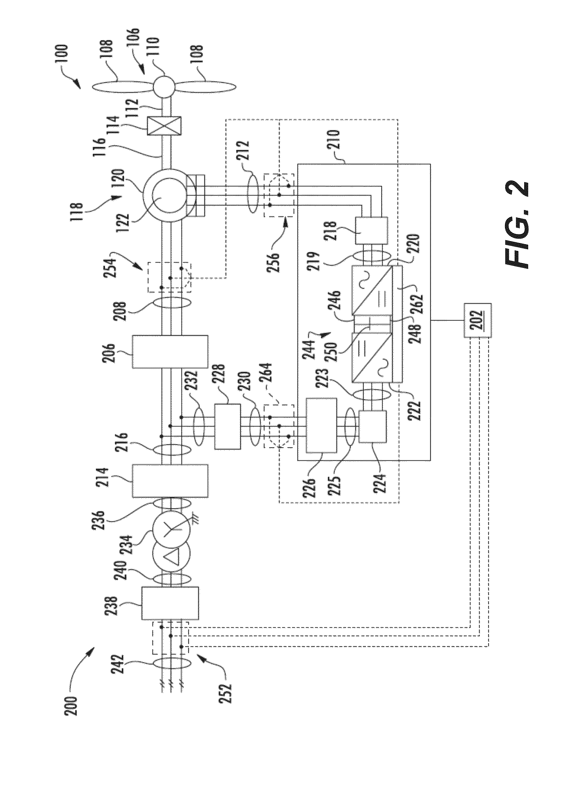
[0023]In general, the present subject matter is directed to an automated apparatus and method for testing a crowbar circuit within a power converter, e.g. a DC-DC power converter, that is configured to be installed as part of a renewable energy system, e.g....


PUM


Abstract

The present disclosure is directed to an automated apparatus and method for testing a crowbar circuit of power converter. The crowbar circuit includes an anti-parallel diode and a voltage-controlled switching element, e.g. a silicon-controlled rectifier (SCR). The method includes implementing a first test sequence for testing operability of the diode and a second test sequence for testing operability of the voltage-controlled switching element. More specifically, the first test sequence determines a first current-voltage feedback that is indicative of the operability of the diode and the second test sequence determines a second current-voltage feedback that is indicative of the operability of the voltage-controlled switching element.

Description

FIELD OF THE INVENTION[0001]The present disclosure relates generally to renewable energy power systems and, more particularly, to an automated method and apparatus for testing a power converter for use in a renewable energy power system, such as a wind turbine.BACKGROUND OF THE INVENTION[0002]Renewable energy power systems, such as wind energy power systems and solar energy power systems, often include a power converter with a regulated DC link. For example, wind power systems, such as wind driven doubly-fed induction generator (DFIG) systems or full power conversion systems, can include a power converter with an AC-DC-AC topology. Solar power systems can include a power converter that has a DC-DC-AC topology.[0003]An energy storage system can be coupled to the DC link of a power converter in a renewable energy system. The energy storage system can be used, for instance, to apply power to the DC link of the power converter during transient conditions. A switching power supply can be...

Claims


Application Information

Patent Timeline
IPC IPC(8): G01R31/40G01R31/50
CPCG01R31/40G01R31/2607G01R31/2827Y02E10/50G01R31/50G01R19/16538H02S50/10G01R31/42
Inventor BERROTERAN GIL, IGORKLODOWSKI, ANTHONY MICHAELSMITH, DAVIDSEYMOUR, ROBERT ALLENNIEMOELLER, BENJAMIN ARTHUR
Owner GENERAL ELECTRIC CO
Why Eureka
Try Eureka