
White organic light emitting device

a light-emitting device and organic technology, applied in the direction of solid-state devices, semiconductor devices, thermoelectric devices, etc., can solve the problems of limited emission characteristics and lifetime, inability to show sufficient luminance of blue emission layer formed of fluorescent materials in comparison with phosphorescence materials, incomplete transfer, etc., to enhance device life, increase driving voltage, and increase manufacturing cost

Active Publication Date: 2015-10-29
LG DISPLAY CO LTD
View PDF7 Cites 9 Cited by
  • Summary
  • Abstract
  • Description
  • Claims
  • Application Information

AI Technical Summary

Benefits of technology

This patent describes a new type of organic light emitting device that has multiple layers that emit light. These layers have evenly distributed emission areas, which can be controlled by a layer that adjusts the output of each layer. This design improves the lifespan of the device and makes it more efficient at emitting light. Overall, this patent provides a way to create a longer-lasting and more powerful organic light emitting device.

Problems solved by technology

For this reason, the blue emission layer formed of a fluorescent material cannot show sufficient luminance in comparison with a phosphorescence material.
In a related art organic light emitting device, emission characteristic and lifetime are limited due to emission structure and material of an organic emission layer.
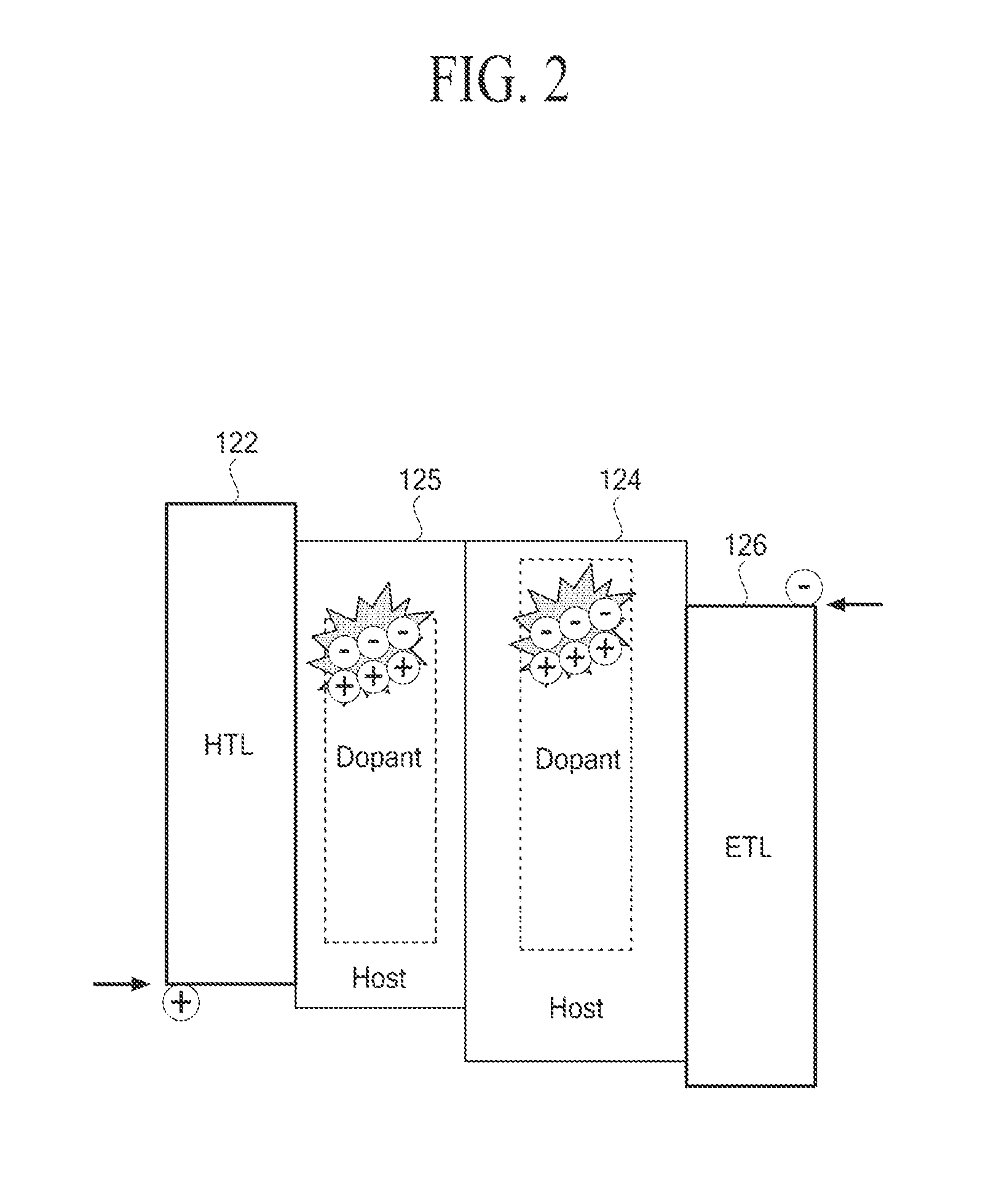
However, the energy transfer is incomplete to a dopant, and it is difficult to adjust a balance of white.
Moreover, a component of a dopant included in a corresponding emission layer is limited due to a characteristic of a dopant itself.
For this reason, a color range capable of expression is narrowed, and consequently, it is difficult to realize a desired color reproduction ratio.
However, in a structure where the number of emission parts configuring emission layers increases, the manufacturing cost increases due to an increase in the number of processes, resulting in an increase in driving voltage due to an increase in the thickness of the device.

Method used


Image

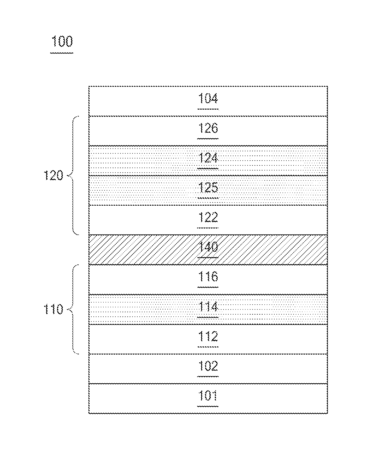
  • White organic light emitting device
  • White organic light emitting device
  • White organic light emitting device

Examples


Embodiment Construction

[0067]Reference will now be made in detail to the exemplary embodiments of the present invention, examples of which are illustrated in the accompanying drawings. Wherever possible, the same reference numbers will be used throughout the drawings to refer to the same or like parts.

[0068]Advantages and features of the present invention, and implementation methods thereof will be clarified through following embodiments described with reference to the accompanying drawings. The present invention may, however, be embodied in different forms and should not be construed as limited to the embodiments set forth herein. Rather, these embodiments are provided so that this disclosure will be thorough and complete, and will fully convey the scope of the present invention to those skilled in the art. Further, the present invention is only defined by scopes of claims.

[0069]A shape, a size, a ratio, an angle, and a number disclosed in the drawings for describing embodiments of the present invention ...


PUM


Abstract

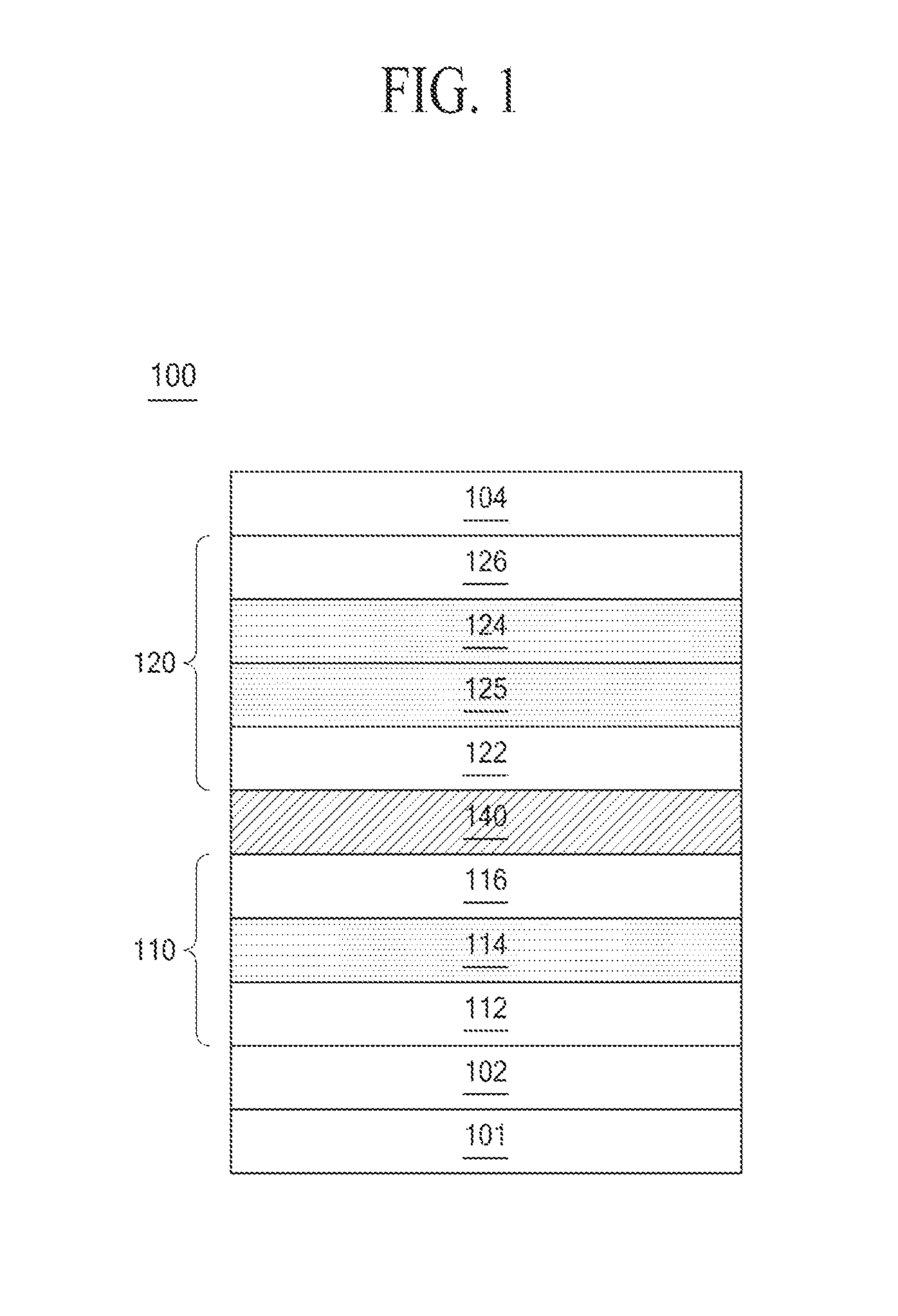
Disclosed is a white organic light emitting device in which a lifetime of a device is enhanced. The white organic light emitting device includes a first emission part between a first electrode and a second electrode and a second emission part on the first emission part. At least one among the first and second emission parts includes an emission area control layer. The white organic light emitting device includes a first emission part between a first electrode and a second electrode, a second emission part on the first emission part, and a third emission part on the second emission part. At least one among the first to third emission parts includes an emission area control layer.

Description

CROSS-REFERENCE TO RELATED APPLICATIONS[0001]This application claims the priority benefit of the Korean Patent Application No. 10-2014-0049867 filed on Apr. 25, 2014, which is hereby incorporated by reference as if fully set forth herein.BACKGROUND[0002]1. Field of the Invention[0003]The present invention relates to an organic light emitting device, and more particularly, to a white organic light emitting device in which a lifetime of a device is enhanced.[0004]2. Discussion of the Related Art[0005]Recently, as society advances to the information-oriented society, the field of display apparatuses, which visually express an electrical information signal, is rapidly advancing. Flat panel display (FPD) apparatuses, having excellent performance in terms of thinness, lightness, and low power consumption, have been developed.[0006]Examples of the FPD apparatuses include LCD apparatuses, plasma display panel (PDP) apparatuses, field emission display (FED) apparatuses, organic light emittin...

Claims


Application Information

Patent Timeline
IPC IPC(8): H01L51/50
CPCH01L51/504H10K50/131H10K59/32H10K50/13H10K50/19H10K2101/90H10K50/11H10K50/15H10K50/16H10K50/155H10K50/156H10K59/123
Inventor SONG, JAE ILKIM, DONG HYUKAHN, SO YEON
Owner LG DISPLAY CO LTD
Learn More