Electrolyte Solutions For Electrochemical Energy Devices

a technology of electrochemical energy devices and electrolyte solutions, which is applied in the direction of non-aqueous electrolyte cells, cell components, electrochemical generators, etc., can solve the problems of limited improvement in some characteristics, difficult to realize a practical battery from a comprehensive viewpoint, and inability to generally use water as a solvent for electrolytic or electrolyte solutions, etc., to achieve high charge/discharge rate capability, improve safety characteristics, and improve performan

Inactive Publication Date: 2008-07-03
3M INNOVATIVE PROPERTIES CO
View PDF6 Cites 14 Cited by
  • Summary
  • Abstract
  • Description
  • Claims
  • Application Information

AI Technical Summary

Benefits of technology

[0008]There remains in the industry a need for electrolyte solutions for electrochemical energy devices, including lithium secondary batteries, that are fire resistant and exhibit improved safety characteristics; that exhibit improved performance including high charge / discharge rate capability at ambient and low temperatures; and for which such safety and performance advantages are not attained at the expense of other required characteristics of the device. There is also a need for electrochemical energy devices with improved electrode charge / discharge cycling efficiencies and prolonged device lifetimes.
[0018]In other aspects, the invention provides electrochemical energy devices, including secondary lithium batteries, employing electrolyte solutions such as those described above. Such electrochemical energy devices can be made to be fire resistant and exhibit improved performance including improved charge / discharge rate capability at ambient and low temperatures. The electrochemical energy devices of the invention can also exhibit improved electrode charge / discharge efficiencies and prolonged device lifetimes.

Problems solved by technology

Water cannot generally be used as a solvent for an electrolytic or electrolyte solution used in such high-voltage electrochemical energy devices, because hydrogen and oxygen are generated as a result of electrolysis.
However, as explained below, technology so far has achieved only limited improvement in some characteristics while sacrificing other properties, and it has been difficult to realize a practical battery from a comprehensive viewpoint.
However, the fluorinated solvent disclosed in this document is not restricted in its boiling point, and numerous compounds are encompassed which tend to cause deterioration in the characteristics of the battery at high temperatures.
Such compounds are detrimental at high temperatures, because vaporization of the solvent causes an increase in internal battery pressure and a deterioration in battery characteristics.
The major problem with using metal lithium for the negative electrode is that the reversibility of lithium deposition / dissolution with charge / discharge is not satisfactory for the purpose of manufacturing a practical secondary battery.
Specifically, generation of lithium dendrites during repeated charge / discharge cycles results in formation of inactive lithium or internal shorting of the cell.
The flash points of THF and THP are, however, −17° C. and −15° C., respectively, and therefore nonaqueous electrolyte solutions using them are readily susceptible to ignition.

Method used


Image

  • Electrolyte Solutions For Electrochemical Energy Devices
  • Electrolyte Solutions For Electrochemical Energy Devices
  • Electrolyte Solutions For Electrochemical Energy Devices

Examples


examples

[0069]The present invention will now be explained by examples. The following abbreviations are used throughout the examples.

[0070]Ethylene carbonate (“EC”)

[0071]Propylene carbonate (“PC”)

[0072]Diethyl carbonate (“DEC”)

[0073]Ethyl methyl carbonate (“EMC”)

[0074]Dimethoxyethane (“DME”)

[0075]Tetrahydrofuran (“THF”)

[0076]Tetrahydropyran (“THP”)

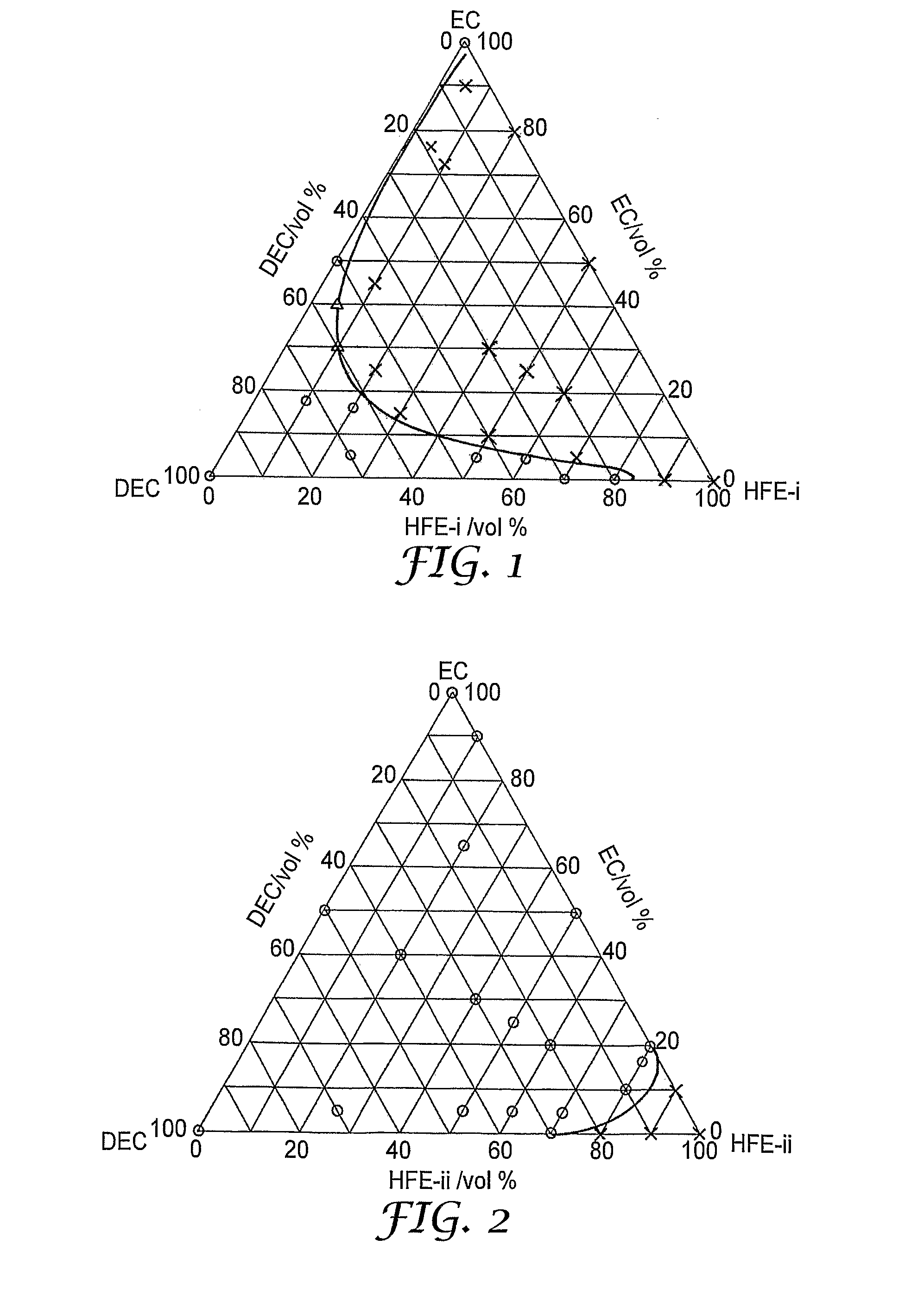
[0077]C2F5CF(CF(CF3)2—OCH3 (“HFE-i”)

[0078]CF3CFHCF2OC2H4OCF2CFHCF3 (“HFE-ii”)

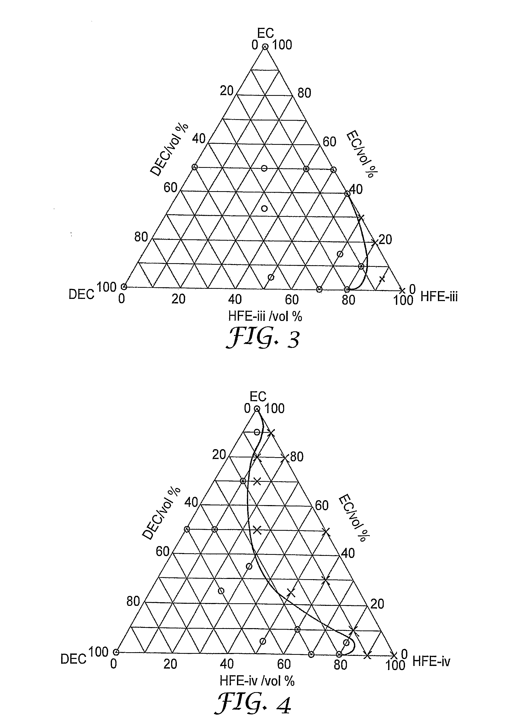
[0079]CF3CFHCF2OCH2CH2CH2OCF2CFHCF3 (“HFE-iii”)

[0080]CH3—O—C6F12—O—CH3 (“HFE-iv”)

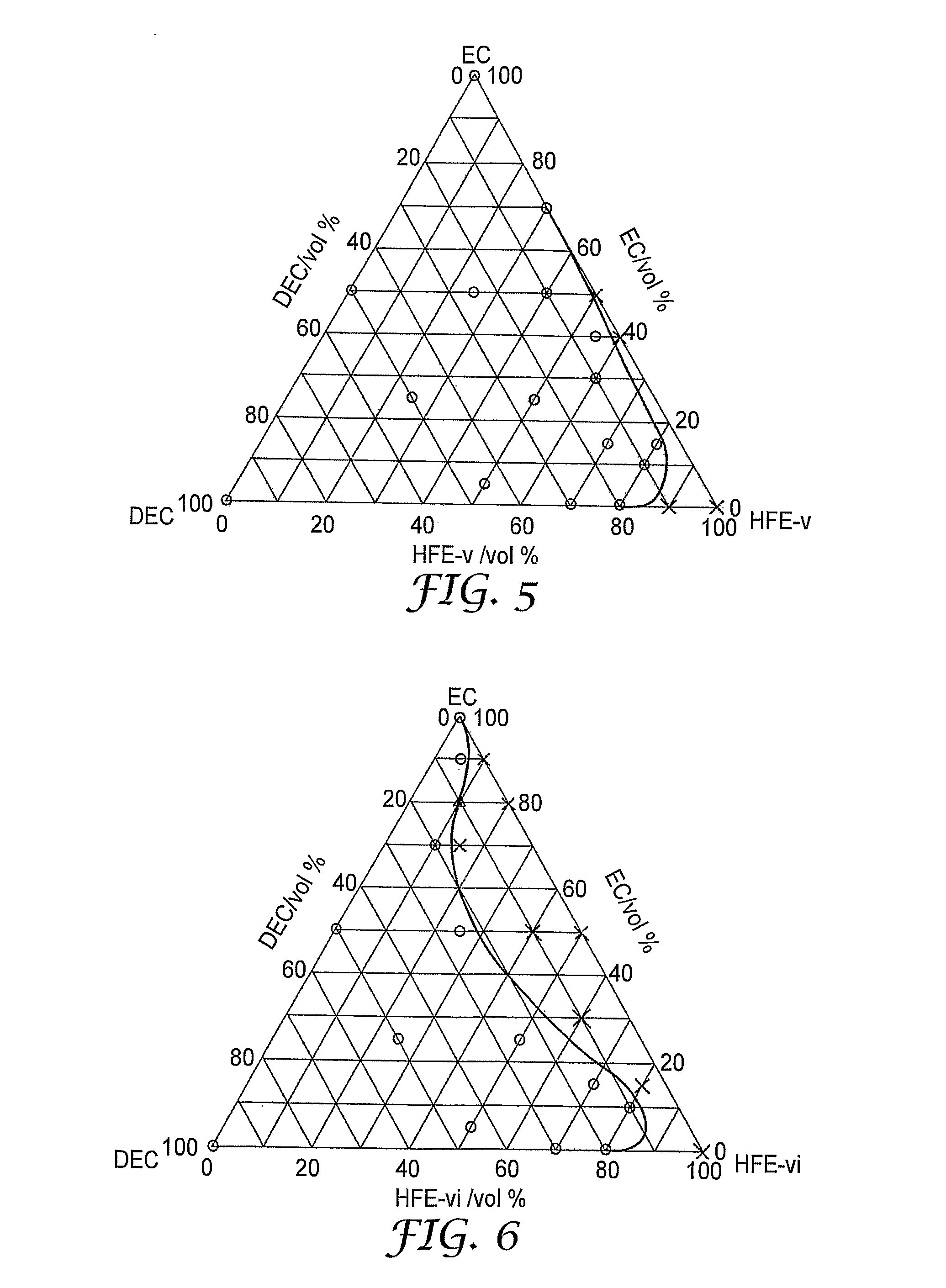
[0081]H—C6F12—CH2—O—CH3 (“HFE-v”)

[0082]H—C8F16—CH2—O—CH3 (“HFE-vi”)

[0083]C3F7—O—C2HF3—O—C2H4—O—C2HF3—O—C3F7 (“HFE-vii”)

[0084]C2HClF3—O—C2H4—O—C2HClF3 (“HFE-viii”)

[0085]CF3CFHCF2—O—CH2CH(CH3)—O—CF2CFHCF3 (“HFE-ix”)

[0086]CF3—CFHCF2—O—CH2CH(OCF2CFHCF3)—CH2—O—CF2CFHCF3 (“HFE-x”)

[0087]CF2HCF2—O—C2H4—O—CF2CF2H (“HFE-xi”)

[0088]Lithium bis(pentafluoroethanesulfonyl)imide (FLUORAD FC-130 or FLUORAD 13858 by Sumitomo 3M Co., Ltd.) (“LiBETI”)

[0089]Lithium hexafluorophosphate (LiPF6)

[0090]Lithium bis(trif...

experiment b (

Lithium Deposition / Dissolution Cycle Efficiency)

[0103]Using a nickel foil punched out into a circle as the working electrode (5 μm thickness, 16.16 mm diameter, 2.05 cm2 area on each side) and metal lithium punched out into a circle (0.3 mm thickness, 16.16 mm diameter, 2.05 cm2 area on each side) as the counter electrode, the electrodes were situated opposite each other across a polypropylene porous separator punched out into a circle (19 mm diameter, 25 μm thickness), to fabricate a coin-type two-electrode cell. The nonaqueous electrolytes used were those shown in Table B. First, lithium was deposited on a nickel plate for 1 hour or 3 hours at a current density of 0.2 mA / cm2 based on the electrode area, followed by a 10 minute rest period. Next, the lithium on the nickel plate was dissolved up to a cell voltage of 1.5 V at a current density of 0.2 mA / cm2, followed by a 10 minute rest period. This lithium deposition / dissolution process was defined as one cycle, and either 15 or 30 ...


PUM

PropertyMeasurementUnit
boiling pointaaaaaaaaaa
voltageaaaaaaaaaa
boiling pointsaaaaaaaaaa

Abstract

Electrolyte solutions for an electrochemical energy device, including a lithium secondary battery, comprising (a) a supporting electrolyte salt and (b) a solvent composition comprising (1) at least one of a cyclic carbonic acid ester solvent and (2) at least one fluorine-containing solvent having a boiling point of at least 80° C., selected from among the following chemical formulas (i) to (iii): (i) R1—O—Rf1; (ii) R2—O—(Rf2—O)p—(Rf3—O)q—R3; (iii) A—(O—Rf4)m (where the definition of each formula is as described in the claim)

Description

FIELD[0001]The present invention relates to electrolyte solutions for electrochemical energy devices.BACKGROUND[0002]Electrochemical energy devices can be made in a variety of capacities and types. For example, devices where the charging or discharging voltage of a unit cell exceeds 1.5 V include lithium primary batteries, lithium secondary batteries, lithium ion secondary batteries, lithium ion gel polymer batteries (sometimes called lithium polymer batteries or lithium ion polymer batteries) and high-voltage electric double layer capacitors (those where the voltage at charging exceeds 1.5 V). Water cannot generally be used as a solvent for an electrolytic or electrolyte solution used in such high-voltage electrochemical energy devices, because hydrogen and oxygen are generated as a result of electrolysis. Therefore, a non-aqueous electrolytic solution obtained by dissolving a supporting electrolyte salt in an aprotic solvent such as an alkyl carbonate or an alkyl ether is generall...

Claims


Application Information

Patent Timeline
Patent Type & Authority Applications(United States)
IPC IPC(8): H01M10/40H01M4/02H01M4/40H01M10/05H01M10/052H01M10/0525H01M10/0568H01M10/0569
CPCH01M10/0525H01M10/0569Y02E60/122H01M2300/0037H01M2300/0025Y02E60/10H01M6/16
Inventor SEGAWA, HARUKILAMANNA, WILLIAM M.COSTELLO, MICHAEL G.
Owner 3M INNOVATIVE PROPERTIES CO
Why Eureka
Try Eureka