
Distribution of corona igniter power signal

a technology of power signal and corona, which is applied in the direction of corona discharge, sparking plugs, machines/engines, etc., can solve the problems of limited use of this design and increase the size and complexity of the corona discharge ignition system

Active Publication Date: 2015-10-29
FEDERAL MOGUL IGNITION
View PDF10 Cites 34 Cited by
  • Summary
  • Abstract
  • Description
  • Claims
  • Application Information

AI Technical Summary

Benefits of technology

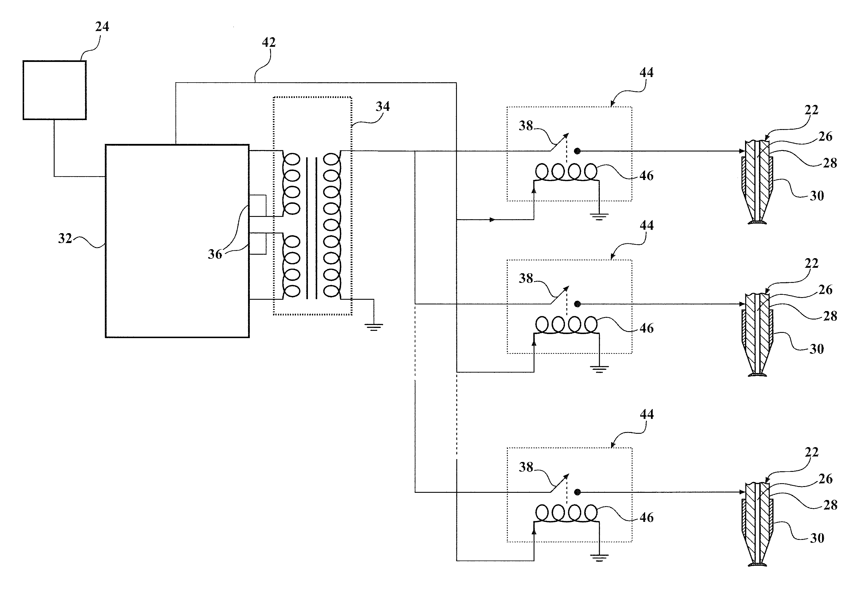
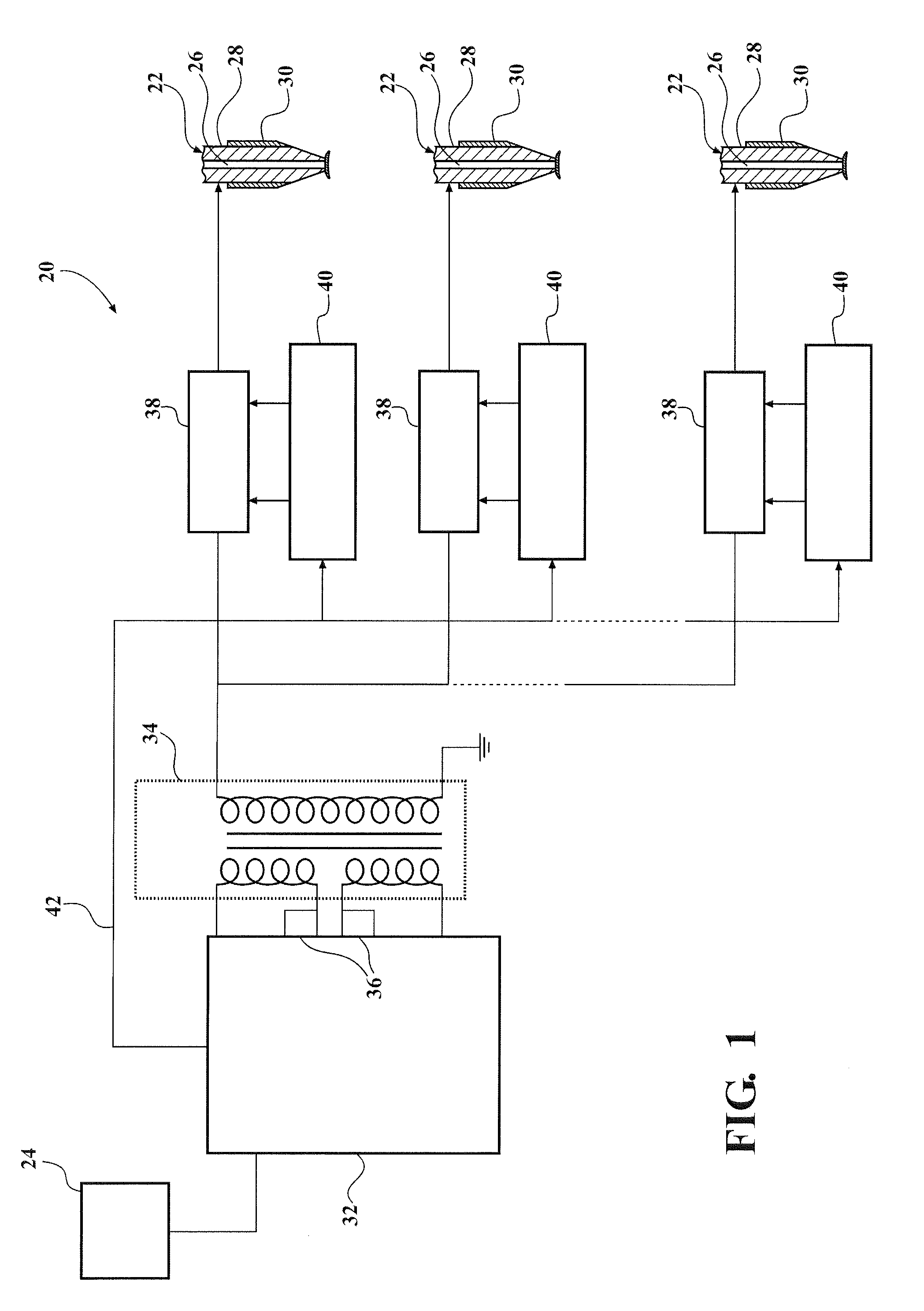
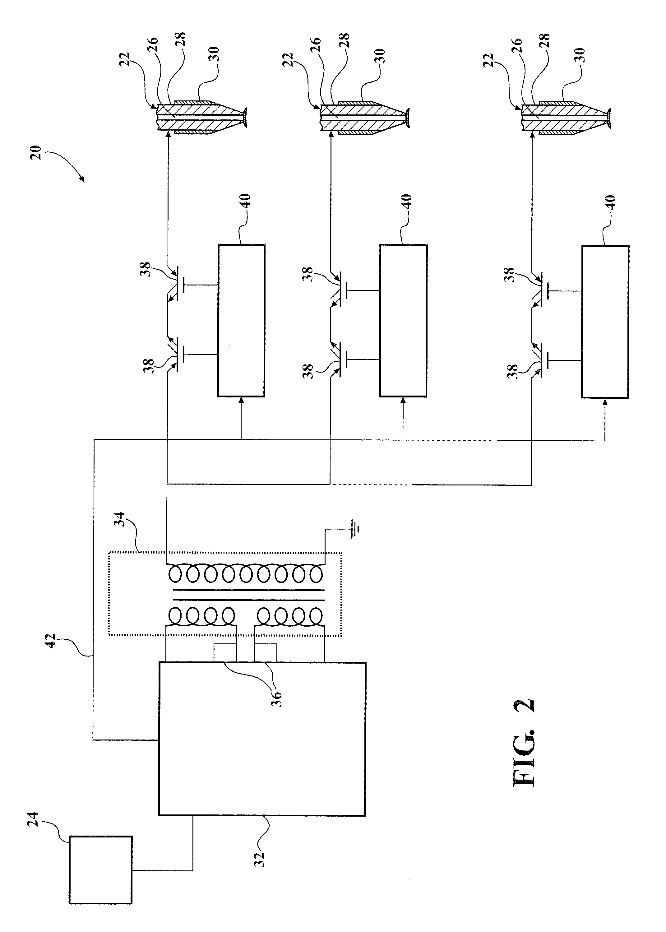
The patent text describes a system that uses electromechanical relays to control the operation of corona igniters. The system receives a control signal from a control and drive electronics unit, which activates or deactivates the igniter switching unit of each relay to allow or prevent energy from traveling from a transformer to the corona igniter. The technical effects of this system are improved control and efficiency of the corona igniters, which can be controlled more precisely and at greater distance from the control and drive electronics unit.

Problems solved by technology

However, use of this design is limited as each transformer is expensive and increases the size and complexity of the corona discharge ignition system.

Method used


Image

  • Distribution of corona igniter power signal
  • Distribution of corona igniter power signal
  • Distribution of corona igniter power signal

Examples


Embodiment Construction

[0014]One aspect of the invention provides a corona discharge ignition system 20 comprising a plurality of corona igniters 22 with reduced costs and complexity. FIGS. 1-3 illustrate exemplary embodiments of the system 20. Each of the corona igniters 22 receives energy from a power supply 24 and oscillates at a resonant frequency, thereby providing a high voltage alternating electric field capable of providing a corona discharge. Each of the corona igniters 22 includes an electrode 26 for receiving the energy and emitting the alternating electrical field to provide the corona discharge. An insulator 28 surrounds the electrode 26, and a metal shell 30 typically surrounds the insulator 28. Any type of corona igniter 22 can be used in the system 20 of the present invention.

[0015]The system 20 includes a control and drive electronics unit 32 for receiving the energy from the power supply 24 and directing the energy toward the corona igniters 22. A single transformer 34 is disposed betwee...


PUM


Abstract

A corona discharge ignition system comprising a plurality of corona igniters is provided. The system includes a control and drive electronics unit for directing the energy from a power supply toward the corona igniters; and a single transformer disposed between the control and drive electronics unit and the plurality of corona igniters. A plurality of igniter switching units is connected to the control and drive electronics unit and each igniter switching unit is connected to a separate one of the corona igniters. Each igniter switching unit allows current to travel from the transformer to the one connected corona igniter when activated and prevents current from traveling from the transformer to the one connected corona igniter and from the one connected corona igniter toward the transformer when deactivated. Only one of the igniter switching units is activated at any given time during operation of the system.

Description

CROSS REFERENCE TO RELATED APPLICATION[0001]This application claims the benefit of U.S. Provisional Patent Application Ser. No. 61 / 985,709 filed Apr. 29, 2014, which is hereby incorporated by reference in its entirety.BACKGROUND OF THE INVENTION[0002]1. Field of the Invention[0003]This invention relates generally to a corona discharge ignition system, and more particularly to a system and method for supplying energy to a plurality of corona igniters of the corona discharge ignition system.[0004]2. Related Art[0005]Corona discharge ignition systems provide an alternating voltage and current, reversing high and low potential electrodes in rapid succession which enhances the formation of corona discharge and minimizes the opportunity for arc formation. The system typically includes a transformer receiving energy from a power supply in the form of a direct current, amplifying the voltage, and reducing the current prior to directing the energy in the form of an alternating current toward...

Claims


Application Information

Patent Timeline
IPC IPC(8): H01T19/00
CPCH01T19/00F02P7/03F02P23/04H01T13/44H01T13/36F02P3/01F02P15/08
Inventor BURROWS, JOHN ANTONYSVIMBERSKY, ZDENEKEMIL, ROBERT
Owner FEDERAL MOGUL IGNITION
Learn More