Charge control device and image forming apparatus including charge control device

Active Publication Date: 2015-10-29
KONICA MINOLTA INC
View PDF8 Cites 12 Cited by
  • Summary
  • Abstract
  • Description
  • Claims
  • Application Information

AI Technical Summary

Benefits of technology

[0011]The present invention has an aim of solving the technical problem described above, and in particular aim

Problems solved by technology

This decrease in the charging current amount causes the following kind of power loss (hereafter, “charging loss”) to occur.
Accordingly, the decrease in the charging current amount from the target value at the end stage of the charging means that a portion of power supplied from the external power source is lost as heat, i.e. charging loss occurs.
In

Method used


Image

  • Charge control device and image forming apparatus including charge control device
  • Charge control device and image forming apparatus including charge control device
  • Charge control device and image forming apparatus including charge control device

Examples


Example

[0031]The following describes a preferred embodiment of the present invention with reference to the drawings.

Overview of Configuration of Image Forming Apparatus

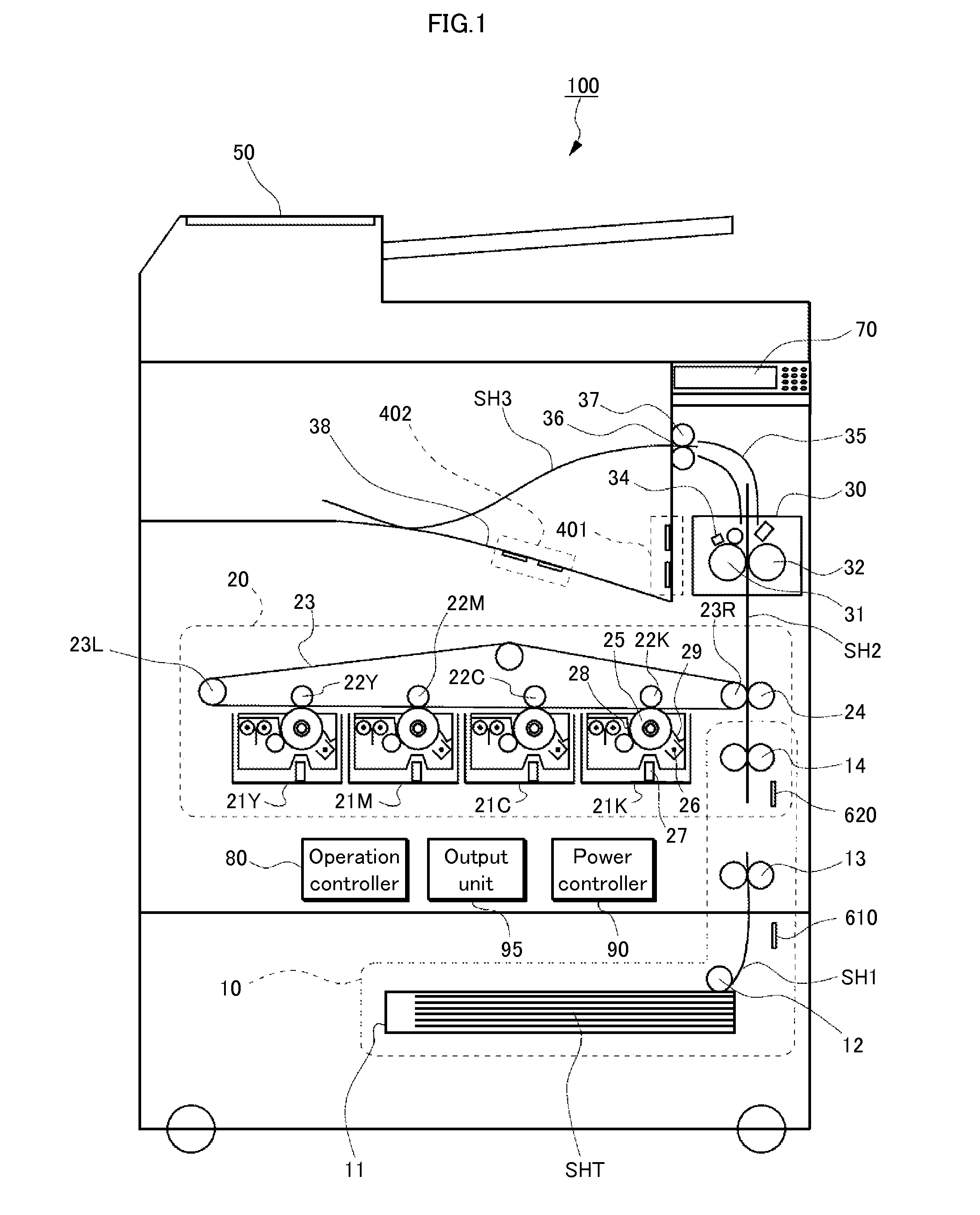
[0032]FIG. 1 is a schematic frontal view illustrating a configuration of an image forming apparatus according to an embodiment of the present invention. Internal elements of an image forming apparatus 100 in FIG. 1 are drawn to be visible as if a front of a housing is transparent.

[0033]Referring to FIG. 1, the image forming apparatus 100 is, for example, a color laser printer, and includes a feeder 10, an imager 20, a fixer 30, generators 401, 402, 50, 610, and 620, an operation unit 70, an operation controller 80, a power controller 90, and an output unit 95. The feeder 10 feeds sheets SHT, sheet by sheet, to the imager 20. The imager 20 forms a toner image on a sheet SH2 fed from the feeder 10. The fixer 30 thermally fixes the toner image. The generators 401, . . . , 620 generate electricity by using surrounding heat, ligh...


PUM


Abstract

A charge control device uses external electricity to charge a plurality of battery devices. A constant current source uses the external electricity to generate and adjust an output current amount to a constant target value. A selector selects one battery device from the plurality of battery devices and supplies output current from the constant current source to the one battery device. A measurer measures an amount of actual current flowing from the constant current source to the one battery device. An instructor monitors a measured value provided by the measurer and instructs the selector, when the measured value meets a condition for a reduction of charging current amount to be regarded as having occurred, to change a destination to which the output current of the constant current source is supplied from the one battery device to a different battery device.

Description

[0001]This application is based on an application No. 2014-091366 filed in Japan, the contents of which are hereby incorporated by reference.BACKGROUND OF THE INVENTION[0002](1) Field of the Invention[0003]The present invention relates to battery devices and charge control.[0004](2) Background[0005]With recent increase in interest in energy conservation, energy harvesting is attracting attention. “Energy harvesting” is a technique of recovering and re-using as electrical power natural energy such as solar, wind, hydro, and geothermal energy, or energy such as vibrations, heat, light, and electromagnetic waves released into the surrounding environment from artificial systems such as machines and factories. Energy harvesting is expected to be of use not only in a power source for sensors, mobile devices, etc., but also in an auxiliary power source in equipment using a commercial power source as a primary power source. For example, the image forming apparatus disclosed in Japanese Pate...

Claims


Application Information

Patent Timeline
IPC IPC(8): H02J7/00G03G15/00
CPCH02J7/0021G03G15/80H02J7/007H02J7/0019H02J7/0047
Inventor TATSUMOTO, YUHEITAMURA, TOMONOBUTESHIMA, SATOSHI
Owner KONICA MINOLTA INC
Why Eureka
Try Eureka