Method of forming a vehicle body structure from a pre-welded blank assembly

a pre-welded and blank technology, applied in the field of vehicle body structures, can solve the problems of severe distortion, concomitant deformation of the base blank and the patch blank, etc., and achieve the effects of facilitating optional welding practices, minimizing or eliminating gaps and separations between the blanks, and promoting strength

Inactive Publication Date: 2015-11-05
GM GLOBAL TECH OPERATIONS LLC
View PDF97 Cites 10 Cited by
  • Summary
  • Abstract
  • Description
  • Claims
  • Application Information

AI Technical Summary

Benefits of technology

[0006]Pre-welding the base blank and the patch blank together, and then concurrently deforming the two blanks into the vehicle body structure, achieves interfacial surface mating between the blanks. To be specific, in some instances, a zero-gap surface-to-surface abutment may be attained between the base blank and the patch blank, even at sharply radiused portions of the vehicle body structure where the two blanks overlap, due to the fact that the two blanks are deformed together. Such intimate interfacial mating promotes strength by minimizing or eliminating gaps and separations between the blanks. It also facilitates the optional welding practices that may follow deformation because the blanks exhibit good interfacial mechanical contact that may be desirable for these practices.
[0007]The disclosed method can simplify the overall manufacturing operation of the vehicle body structure as well. In particular, the coordinated operation of two separate metalworking processes—one for the base blank and one for the patch blank—can be eliminated since the base blank and the patch blank are deformed concurrently by the same metalworking process. Deforming the two blanks at the same time can also obviate the need to practice the types of cumbersome tuning techniques that are so commonly employed to improve the fit between separately deformed blanks. These process-related attributes, as well as others, enable a manufacturing operation that is practical, cost-effective, and able to consistently produce vehicle body structures with little variance.

Problems solved by technology

The stamping process may be configured to result in concurrent deformation of the base blank and the patch blank with the most severe distortions occurring away from the series of spot-welds and outside of the heat-affected zone attributed to the spot welds.

Method used


Image

  • Method of forming a vehicle body structure from a pre-welded blank assembly
  • Method of forming a vehicle body structure from a pre-welded blank assembly
  • Method of forming a vehicle body structure from a pre-welded blank assembly

Examples


Embodiment Construction

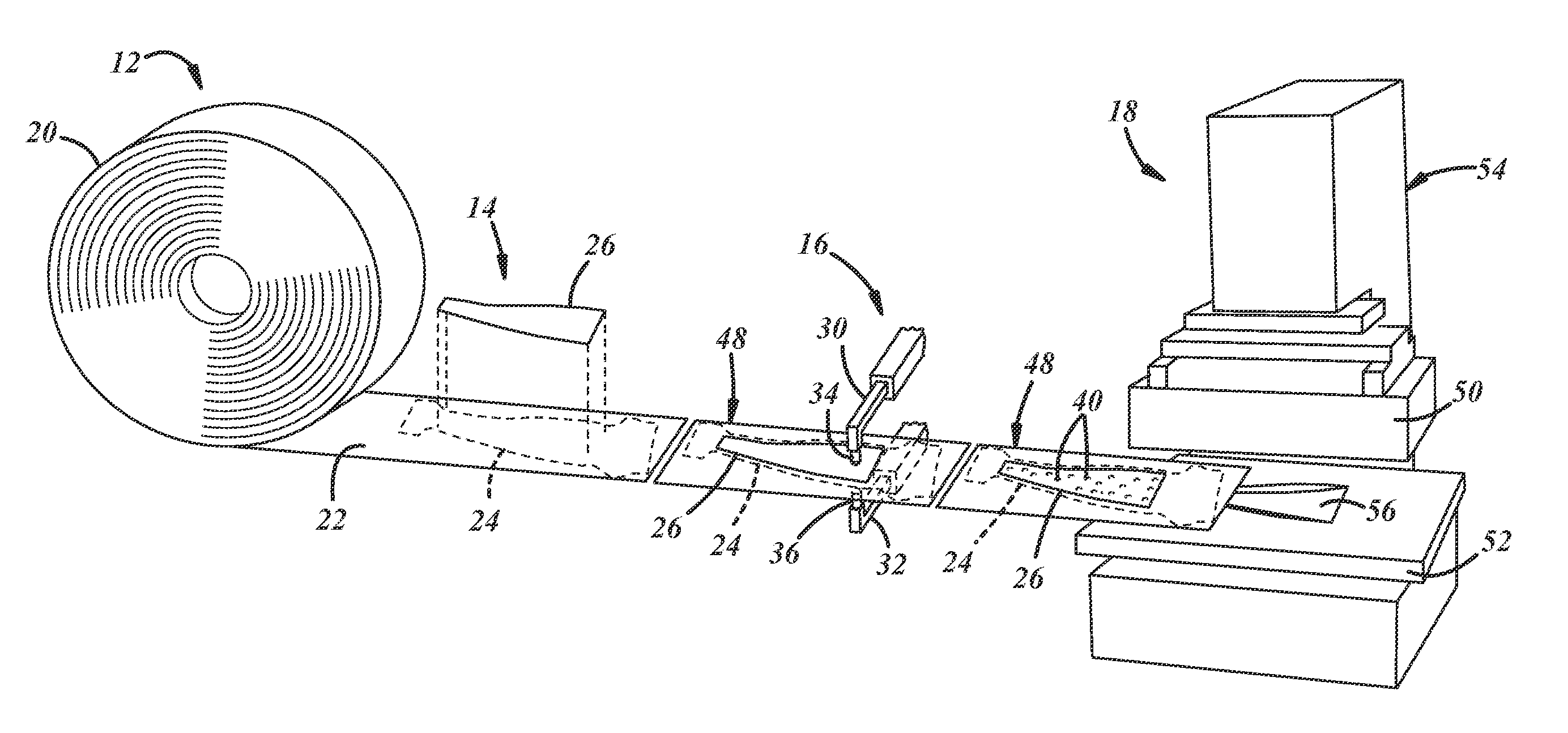
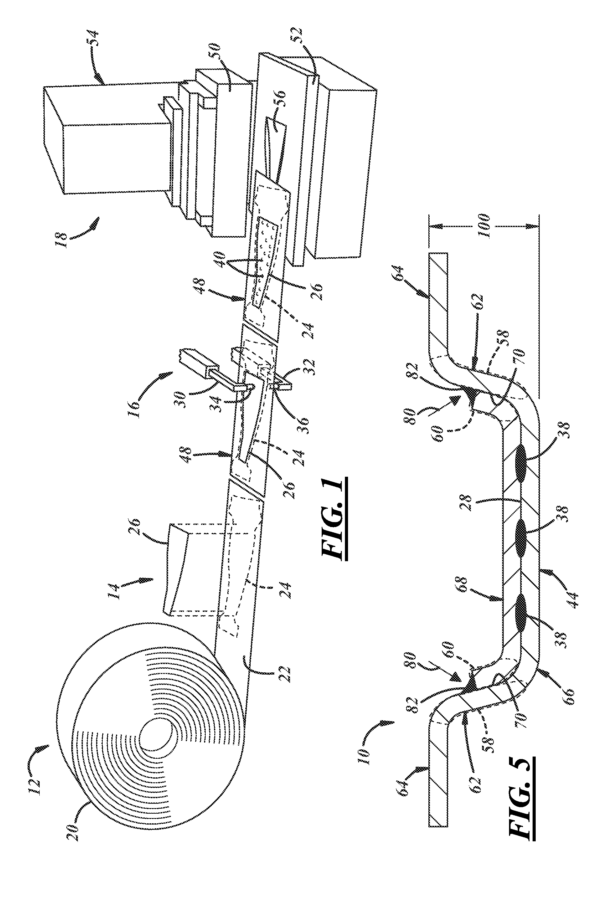
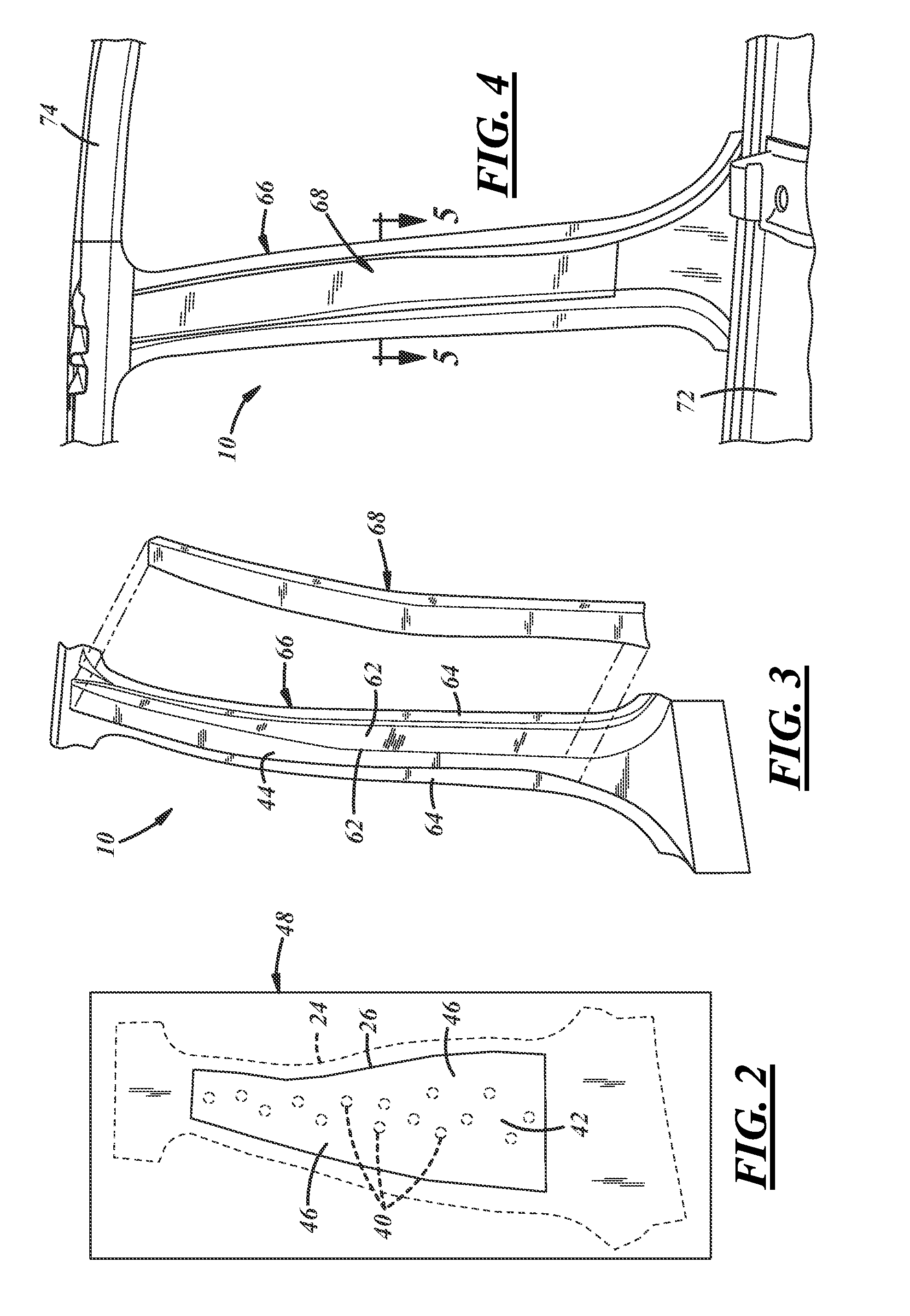
[0014]A method of forming a vehicle body structure is shown and described with reference to FIGS. 1-5. The vehicle body structure described here is a type of automotive support pillar 10 (FIG. 5), known in the industry as a B-pillar, but could be any other body structure made of an aluminum alloy base blank and strengthened with at least one aluminum alloy patch blank. Other such vehicle body structures include an underbody cross-member, a roof frame, and a side member. Furthermore, although the method is depicted and described with certain process steps performed in a certain sequence, more or less steps and different sequences could be carried out in applications not depicted and described here, some of which are set forth below.

[0015]FIG. 1 schematically depicts a preferred method, along with related equipment, for forming the automotive support pillar 10. The illustrated method includes a dereeling step 12, a placement step 14, a pre-welding step 16, a deforming step 18, and opt...


PUM

PropertyMeasurementUnit
thicknessesaaaaaaaaaa
thickaaaaaaaaaa

Abstract

A method of forming a vehicle body structure includes pre-welding a patch blank to a base blank with a series of resistance spot welds to form a pre-welded blank assembly. After pre-welding, the pre-welded blank assembly is deformed into the vehicle body structure. The deformation of the pre-welded blank assembly is carried out by a suitable metalworking process, such as stamping, and results in concurrent deformation of the base blank and the patch blank. Following deformation of the pre-welded blank assembly, additional weld joints may optionally be formed between the base blank and the patch blank, wherever desired, to better secure the blanks together.

Description

TECHNICAL FIELD[0001]The technical field of this disclosure relates generally to vehicle body structures and, more particularly, to a method of forming vehicle body structures having aluminum alloy base blanks reinforced with aluminum alloy patch blanks.BACKGROUND[0002]The skeleton of a vehicle is comprised of several integrated vehicle body structures. In an automotive vehicle, for instance, the vehicle body structures commonly include underbody cross-members, roof frames, A- and B- and C-pillars, and side members. When secured together, those structures support a wide range of automotive parts including the doors, hood, trunk lid, and quarter panels. The aforementioned vehicle body structures may include a base blank that is reinforced with a patch blank to provide additional structural supported at targeted locations, with each blank conventionally being made of steel.[0003]Automotive manufacturers have recently begun to substitute aluminum alloys for steel wherever possible to r...

Claims


Application Information

Patent Timeline
Patent Type & Authority Applications(United States)
IPC IPC(8): B21D53/88B23K11/00B23K11/11
CPCB21D53/88B23K11/002B23K11/11B23P15/00B62D25/00B21D22/20B21D35/007B23K11/115B23K26/22B23K26/32B23K2101/006B23K2101/185B23K2103/10
Inventor NELSON, MARK A.CONRAD, LOUIS J.
Owner GM GLOBAL TECH OPERATIONS LLC
Why Eureka
Try Eureka