Lamination method and laminate

a technology of laminate and film thickness, applied in the field of laminate, can solve the problems of insufficient jp 4739558 b in applications requiring high accuracy, lack of versatility, and inability to achieve high film thickness accuracy, reduce film thickness variations, and suppress cost increases

Inactive Publication Date: 2015-11-05
FUJIFILM CORP
View PDF0 Cites 25 Cited by
  • Summary
  • Abstract
  • Description
  • Claims
  • Application Information

AI Technical Summary

Benefits of technology

[0013]The present invention has been made to solve such prior art problems and aims at providing a lamination method which can reduce film thickness variations in a non-metallic substrate to achieve a high film thickness accuracy, ensures high versatility, and can suppress cost increases, as well as a laminate obtained thereby.
[0027]The invention as described above can be applied to a variety of substrates regardless of the substrate material or the like, and can also reduce film thickness variations in a non-metallic substrate to achieve a high film thickness accuracy while suppressing cost increases owing to unnecessary special processing.

Problems solved by technology

However, the film thickness accuracy obtained by the methods described in JP 4368654 B and JP 4739558 B is not sufficient in applications requiring high accuracy.
The method described in each of JP 2009-279909 A and JP 4601918 B achieves a high film thickness accuracy but suffers from lack of versatility due to considerable equipment constraints and cost increases because of the necessity of special processing.

Method used


Image

  • Lamination method and laminate
  • Lamination method and laminate
  • Lamination method and laminate

Examples


example 1

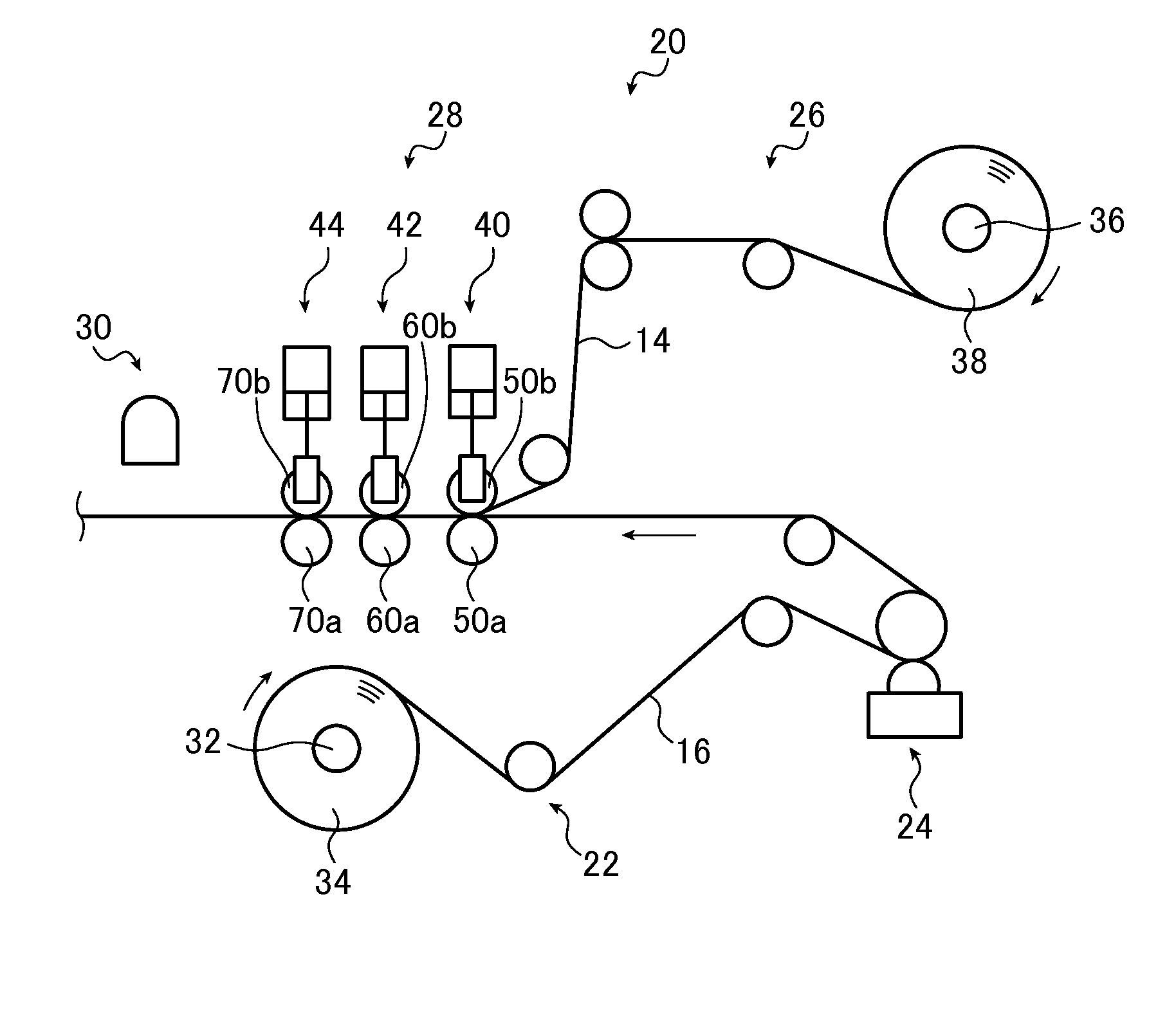
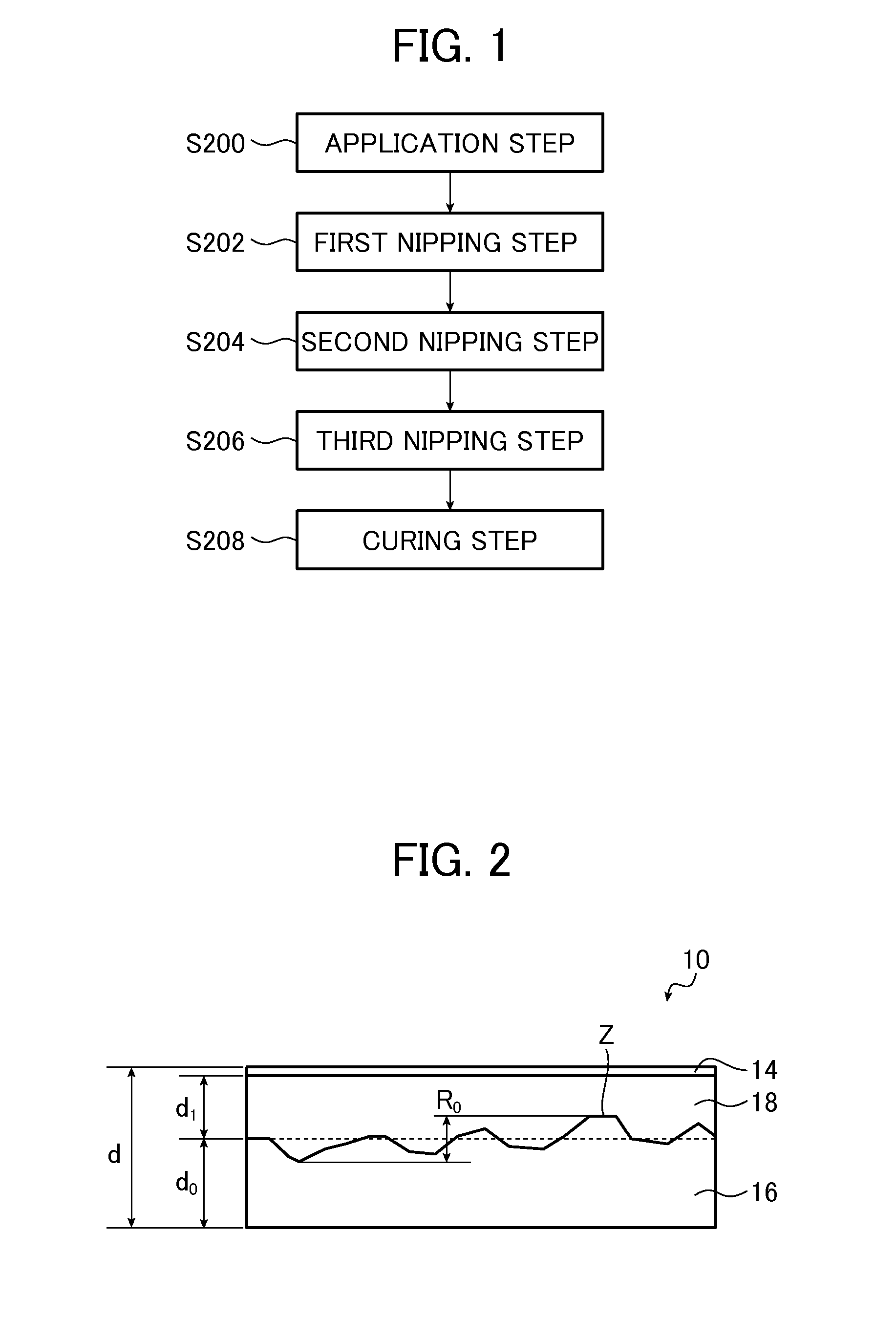
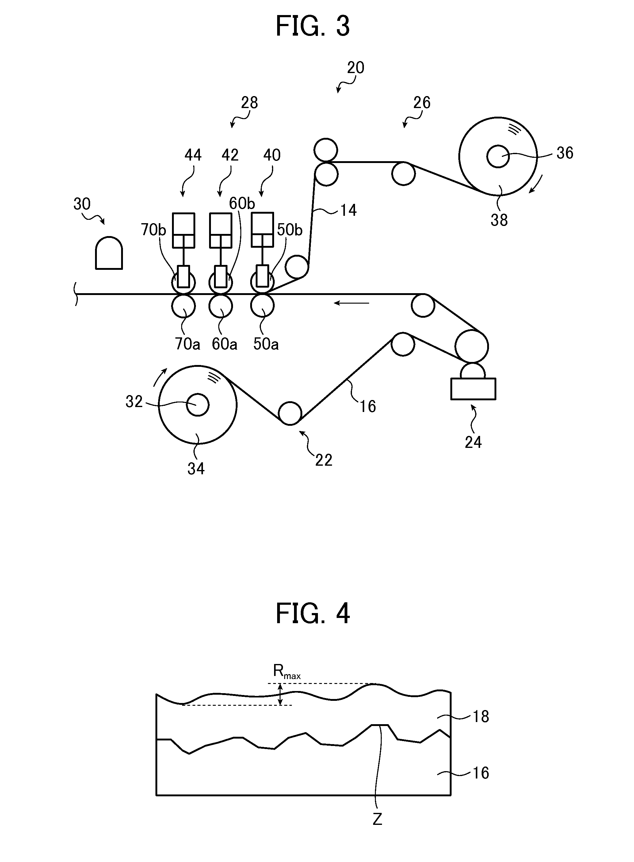
[0151]In Example 1, the laminate 10 was prepared using the laminator 20 shown in FIG. 3.

[0152]The thickness d0 of the substrate 16 and the maximum height R0 at the surface of the substrate 16 were measured by surface scanning with a laser displacement meter before applying an adhesive. The maximum height Rmax upon application of the adhesive was measured by surface scanning with a laser displacement meter after applying the adhesive. The thickness d and the surface roughness R1 of the laminate 10 were each measured by surface scanning with a laser displacement meter after lamination. Three laser displacement meters (LK-H008 manufactured by Keyence Corporation) were disposed in the width direction on a pass roll (not shown) in each of before application, after application and after lamination and measurement was continuously made over 100 m with positions 50 mm inside from the edges and the web center lying on line.

[0153]A rubber sheet having a (Shore A) hardness of 64° and an averag...


PUM

PropertyMeasurementUnit
surface roughnessaaaaaaaaaa
pressureaaaaaaaaaa
viscosityaaaaaaaaaa

Abstract

A lamination method includes: a bonding step of bonding a support to a main surface of a substrate while transporting the substrate and the support along predetermined transport paths; and a curing step of curing an adhesive after the bonding step, and the bonding step is performed to bond the substrate and the support together while sequentially passing the substrate and the support through two or more nip roller pairs and, of the two or more nip roller pairs, a nip roller pair provided downstream has a nip distance set to be equal to or smaller than a nip distance of a nip roller pair provided upstream. The lamination method and a laminate obtained thereby can reduce film thickness variations in a substrate to achieve a high film thickness accuracy, ensures high versatility, and can suppress cost increases.

Description

CROSS-REFERENCE TO RELATED APPLICATIONS[0001]This application is a Continuation of PCT International Application No. PCT / JP2014 / 052695 filed on Feb. 5, 2014, which claims priority under 35 U.S.C. §119(a) to Japanese Application No. 2013-039262 filed on Feb. 28, 2013. Each of the above application(s) is hereby expressly incorporated by reference, in its entirety, into the present application.BACKGROUND OF THE INVENTION[0002]The present invention relates to a lamination method of a non-metallic substrate made of resin, rubber or the like and a laminate. The present invention more specifically relates to a lamination method which improves the film thickness accuracy in a substrate and a laminate.[0003]Rubber sheets and resin sheets suffer from quality variations due to widely varying film thicknesses. Therefore, a variety of manufacturing methods which improve the film thickness accuracy of rubber sheets in manufacturing the rubber sheets have been proposed.[0004]For example, JP 436865...

Claims


Application Information

Patent Timeline
Patent Type & Authority Applications(United States)
IPC IPC(8): B32B37/10B29C65/48B32B37/06B32B7/12B32B25/04B32B37/12B29C65/78
CPCB32B37/1054Y10T428/24959B29C65/4845B29C65/78B32B7/12B32B25/04B32B37/06B32B2367/00B32B2037/1253B32B2250/02B32B2317/22B29L2009/00B29K2607/00B29K2667/003B32B2255/06B32B2255/10B32B37/12B32B37/0053B32B37/20B32B2309/105B32B2310/0806B29C65/526B29C66/1122B29C66/45B29C66/71B29C66/73162B29C66/742B29C66/7422B29C66/74283B29C66/81465B29C66/8242B29C66/83413B29C66/92611B29C66/92653B29C66/92655B29C65/1406B32B2310/0831B32B2310/0875B29C66/73365B29K2067/003
Inventor SATO, HIROSHISHINOZUKA, TOMOYUKI
Owner FUJIFILM CORP
Why Eureka
Try Eureka