
Eureka
For R&D, Eureka makes reading and utilizing patents & technical documents easy.
Eureka AIR
Designed for self-driven R&D workflows. Generate viable solutions, solve complex R&D challenges, empower your innovation with AI.

Eureka Materials
Designed for material experts only. Revolutionize your material R&D, from search, analyze, to developing new materials.

TechResearch
Generate reliable direction feasibility study reports for your R&D in just a few steps.

TechSeek
Discover and master advanced knowledge NOW. Basics, ideas, possibilities, all at once.

TechMind
As an expert in R&D Theories, TechMind can generates customized viable solutions instantly.

TechRisk
Analyze your overall solution with one click, know your potential R&D risks in advance.

TechMonitor
Get weekly tech updates, stay abreast of the latest tech innovations and key insights.
Functional element, physical quantity sensor, electronic apparatus and mobile entity
- Summary
- Abstract
- Description
- Claims
- Application Information
AI Technical Summary
Benefits of technology
Problems solved by technology
Method used
Image

Examples
first embodiment
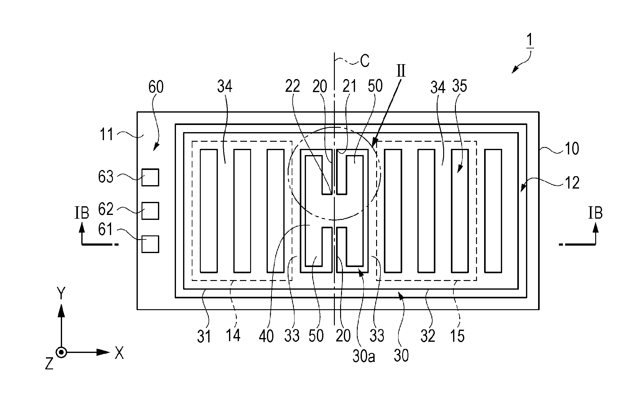
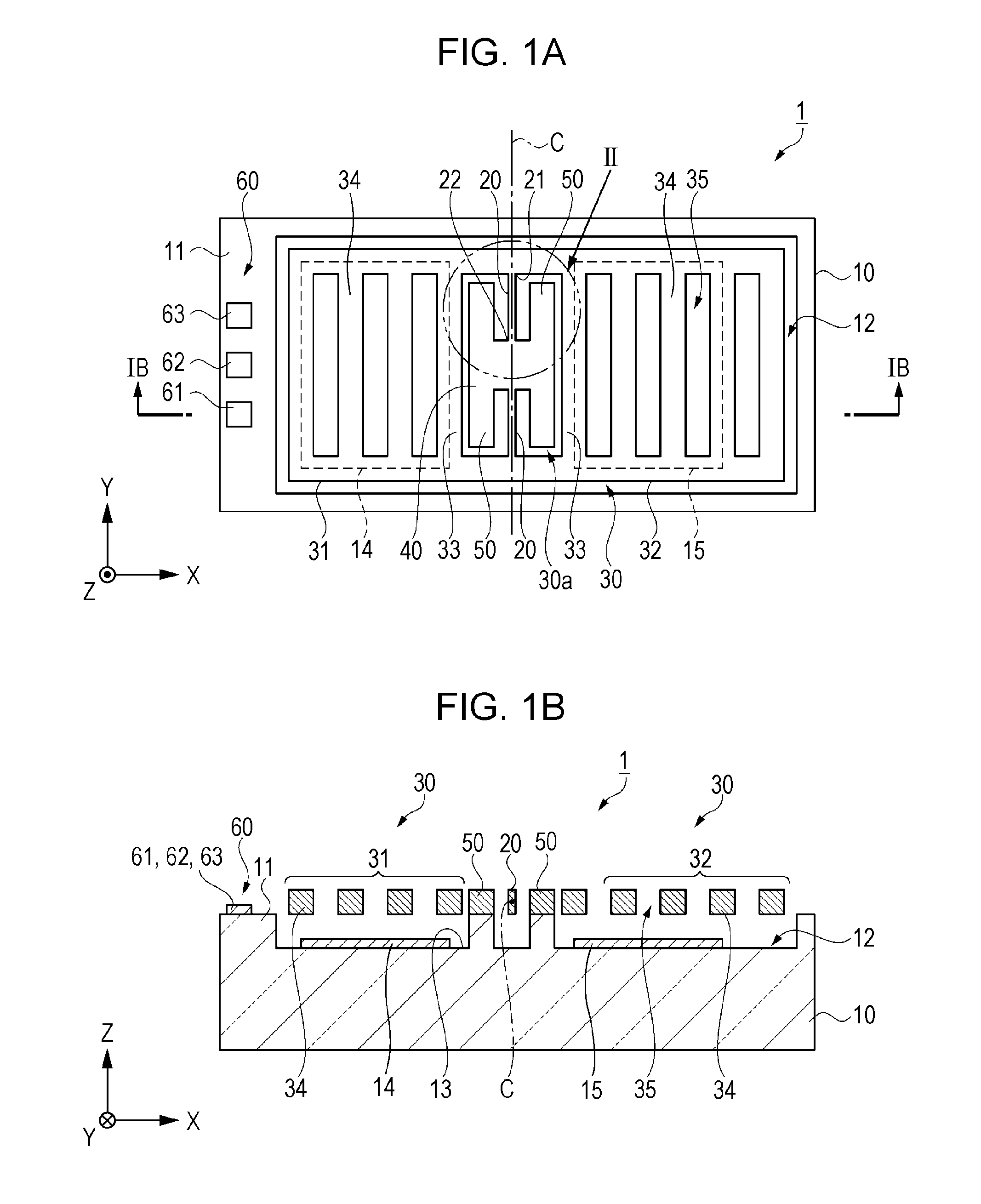
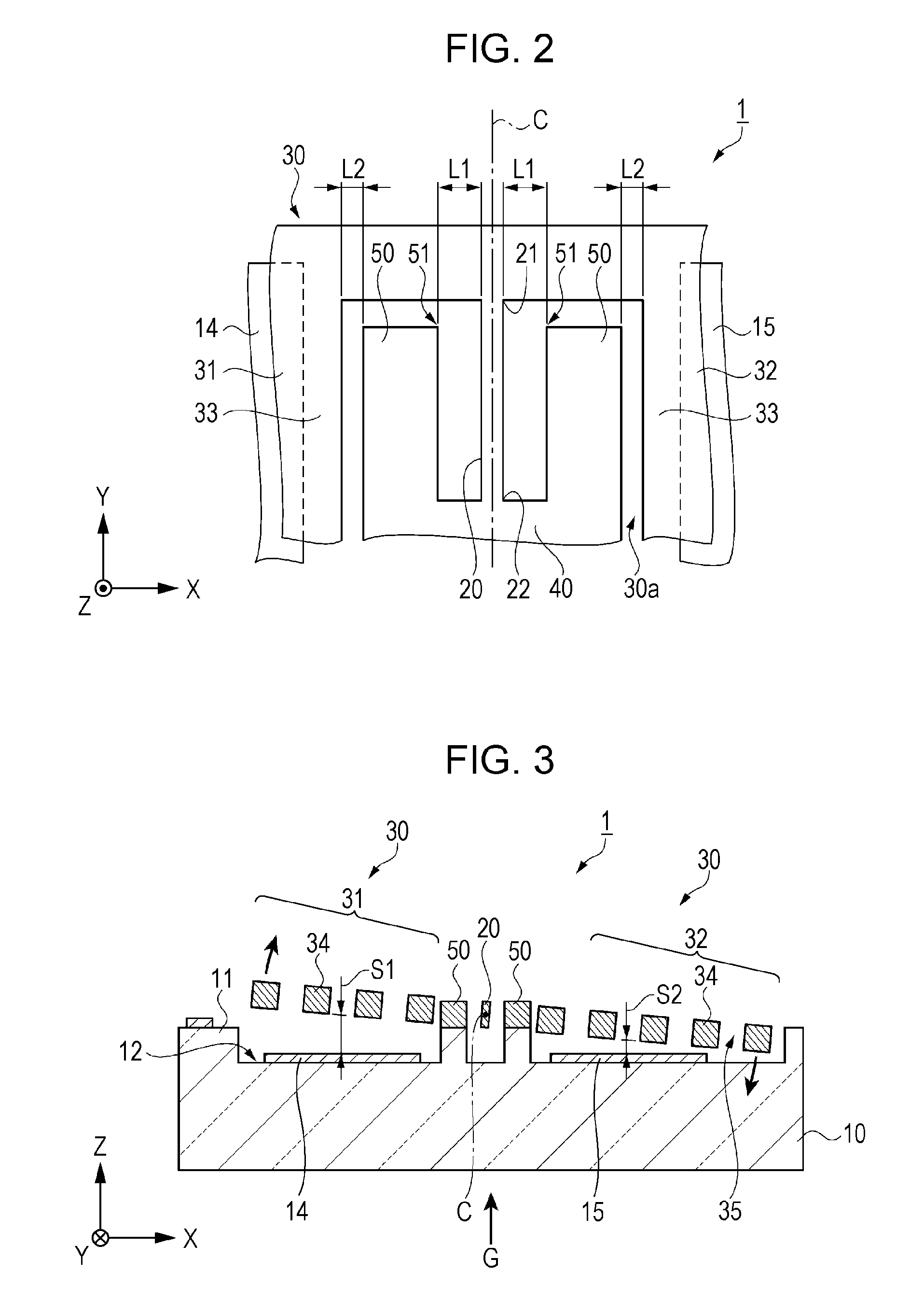
[0058]FIG. 1A and FIG. 1B are schematic views showing a configuration of an acceleration sensor according to one aspect of the first embodiment. FIG. 1A is a schematic plan view and FIG. 1B is a schematic sectional view taken along line IA-IA of FIG. 1A. FIG. 2 is a schematic enlarged view showing portion II surrounded with a two-dotted chain line in FIG. 1A.
[0059]In the respective drawings including and subsequent to FIG. 1A and FIG. 1B, a dimensional proportion of each configuration element may be set to be different from that used in practice in order to facilitate understanding. Further, in the drawings, the X axis, the Y axis and the Z axis are coordinate axes orthogonal to each other, and arrows indicate+directions.
[0060]As shown in FIG. 1A and FIG. 1B, the functional element which is provided in the acceleration sensor 1 includes a substantially rectangular planar substrate 10, a pair of support beams 20, a substantially rectangular planar weight body 30, a stationary section...
first modification example
[0108]FIG. 5 is a schematic plan view showing the main portion of the acceleration sensor according to the first modification example of the first embodiment.
[0109]As shown in FIG. 5, in the acceleration sensor 2 of the first modification example, when seen in the plan view, an angle of a corner section 51 in the engaging section 50 is rounded like an arc shape. Further, in the acceleration sensor 2, the engaging section 50 not shown in the −Y side is also formed to be the same shape as the shown one.
[0110]According to this, the angle of a corner section 51 in the engaging section 50 is rounded like an arc shape in the acceleration sensor 2, when seen in the plan view. Therefore, even if the support beam 20 contacts with the corner section 51 of the engaging section 50, the rounding of the angle causes an impact force to be dispersed and thus it is possible to suppress the damage of the support beam 20.
[0111]Further, a curvature of the arc is appropriately set according to a ratio o...
second modification example
[0112]FIG. 6 is a schematic plan view showing the main portion of the acceleration sensor according to the second modification example of the first embodiment.
[0113]As shown in FIG. 6, in the acceleration sensor 3 of the second modification example, when seen in the plan view, an angle of a corner section 51 in the engaging section 50 is cut off. Further, in the acceleration sensor 3, the engaging section 50 not shown in the −Y side is also formed to be the same shape as the shown one.
[0114]According to this, the angle of a corner section 51 in the engaging section 50 is cut off in the acceleration sensor 3, when seen in the plan view. Therefore, even if the support beam 20 contacts the corner section 51 of the engaging section 50, the cut-off of the angle causes an impact force to be dispersed and thus it is possible to suppress the damage of the support beam 20.
[0115]Further, a cut-off of the corner is appropriately set according to a ratio of L1 to L2, a flexibility of the suppor...
PUM
 Abstract
Description
Claims
Application Information
 - R&D Engineer
- R&D Manager
- IP Professional
- Industry Leading Data Capabilities
- Powerful AI technology
- Patent DNA Extraction
Browse by: Latest US Patents, China's latest patents, Technical Efficacy Thesaurus, Application Domain, Technology Topic, Popular Technical Reports.
© 2024 PatSnap. All rights reserved.Legal|Privacy policy|Modern Slavery Act Transparency Statement|Sitemap|About US| Contact US: help@patsnap.com