Wireless communication method and wireless communication system

Inactive Publication Date: 2015-11-05
HITACHI LTD
View PDF0 Cites 44 Cited by
  • Summary
  • Abstract
  • Description
  • Claims
  • Application Information

AI Technical Summary

Benefits of technology

[0033]According to the invention, in a wireless communication system performing a CA, particularly, a wireless communication system using a macro cell as a lagacy carrier and using a small

Problems solved by technology

However, it is difficult to secure the entire covera

Method used


Image

  • Wireless communication method and wireless communication system
  • Wireless communication method and wireless communication system
  • Wireless communication method and wireless communication system

Examples


first embodiment

1. First Embodiment

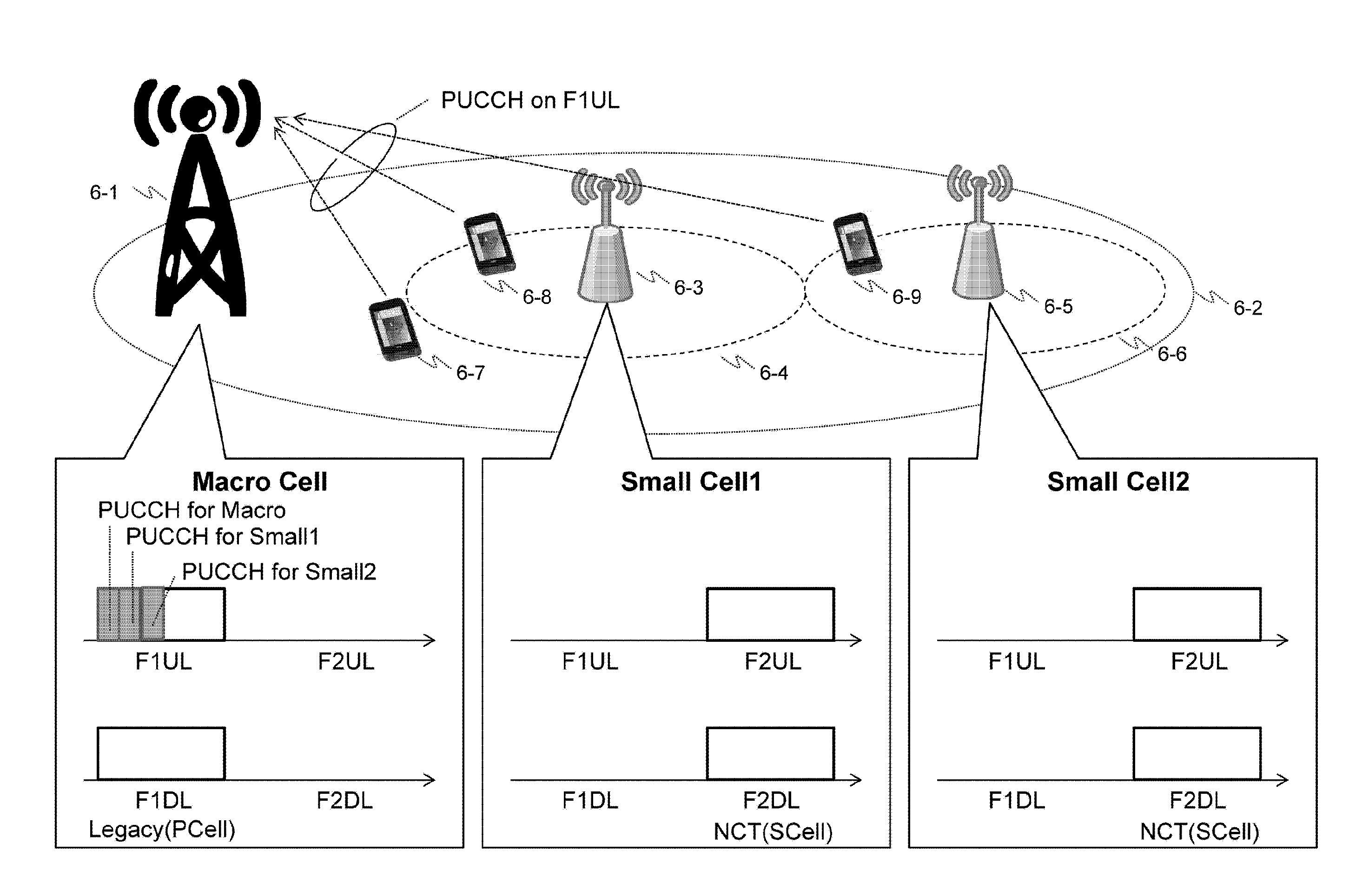
[0053]An object of a first embodiment is to distribute transmission of a PUCCH to a plurality of cells, that is, a plurality of UL CCs.

[0054]FIG. 4 is a schematic diagram of the first embodiment of the invention. Similar to FIG. 3, a lagacy carrier is used in a macro cell 4-2 and an NCT is used in a CC different from the macro cell in a small cell 4-4.

[0055]In FIG. 4, a terminal 4-5 is positioned at only the macro cell 4-2 and performs communication with a macro base station 4-1 using the lagacy carrier (F1DL and F1UL). That is, a PDCCH or an EPDCCH of the F1DL is transmitted from the macro base station 4-1 to the terminal 4-5 and a PDSCH for the terminal 4-5 is scheduled. In addition, in the F1DL, the PDSCH is transmitted from the macro base station 4-1 to the terminal 4-5. Likewise, a PUSCH of the terminal 4-5 is scheduled using the PDCCH or the EPDCCH of the F1DL. In addition, in the F1UL, the PUSCH is transmitted from the terminal 4-5 to the macro base station...

second embodiment

2. Second Embodiment

[0067]An object of a second embodiment is to distribute transmission of a PUCCH to a space, that is, a different cell direction of the same CC.

[0068]In the LTE standard, a PUCCH for each cell is distinguished by a PCI. Specifically, if the PCI is different, initial values of a signal sequence (base sequence) to be a base of a signal sequence of the PUCCH and a random sequence to determine a pattern of cyclic shift are different. Meanwhile, PUCCHs between terminals in the same cell ID are distinguished by PUCCH resources. Specifically, if the PUCCH resources are different, a frequency resource (that is, a number of a PRB) used for the PUCCH, a cyclic shift amount, and an orthogonal sequence multiplied with a time domain are different. The details thereof are disclosed in NPL 3.

[0069]When PCI used in PUCCHs transmitted by different terminals is different, interference of the PUCCHs of the terminals is randomized even though the terminals use the same PUCCH resource...

third embodiment

3. Third Embodiment

[0078]In a third embodiment, an object of a third embodiment is to distribute transmission of a PUCCH to a frequency carrier direction and a space direction.

[0079]In the second embodiment, as illustrated in FIG. 7, only the transmission destination of the PUCCH is changed (that is, the PCI to generate the signal sequence of the PUCCH is changed to the VCI of the different value). For this reason, the PUCCH resources need to be distinguished in the macro cell and the small cell to prevent the PUCCH of the terminal transmitting the PUCCH to the macro cell from causing large interference in the small cell and frequency use efficiency of the uplink in the macro cell may not be sufficiently improved. In addition, in the first embodiment, as illustrated in FIG. 4, only the CC transmitting the PUCCH is changed. For this reason, even though the F2UL is not used for the communication of the data (PUSCH) of the uplink in the macro cell, the macro base station needs to have ...


PUM


Abstract

When a carrier aggregation using a macro cell of a legacy carrier as a primary cell and using a small cell of a new carrier type as a secondary cell is performed, transmission of a control channel (PUCCH) of an uplink is concentrated on an uplink of the macro cell and frequency efficiency is degraded. For this reason, in a state in which the macro cell is configured as the primary cell, a serving cell transmitting the PUCCH is configured to a terminal and the terminal transmits the PUCCH using the configured serving cell.

Description

TECHNICAL FIELD[0001]The present invention relates to a base station performing communication using a plurality of frequency carriers and a wireless communication system.BACKGROUND ART[0002]Recently, development of smart phones or tablet terminals has stimulated concern over a wireless traffic amount increasing explosively. In order to take wireless traffic increasing in this way, it is necessary to improve a capacity of the wireless traffic (wireless communication capacity) that can be taken. As technology for improving the wireless communication capacity, a small cell configuration covering a service area by multiple low transmission power base stations (low power nodes (LPNs)) has attracted attention. In the long term evolution (LTE) standard, a base station may be called an E-UTRAN node B (eNB) and a terminal may be called a user equipment (UE).[0003]The small cell is called a micro cell, a pico cell, or a femto cell and the base station covering the small cell is called a micro...

Claims


Application Information

Patent Timeline
IPC IPC(8): H04W72/04H04W16/32H04W74/00
CPCH04W72/0426H04W74/002H04W84/02H04W88/02H04W88/12H04W16/32H04L5/001H04L5/0053H04L5/0092H04W72/27
Inventor ISHIDA, HITOSHIYAMAMOTO, TOMONORITAMAKI, SATOSHITAMAKI, TSUYOSHI
Owner HITACHI LTD
Why Eureka
Try Eureka