Hydromill wheel with single disc cutting rollers

a technology of cutting rollers and hydromills, which is applied in the direction of earth-moving machines/dredgers, drilling accessories, soil shifting machines/dredgers, etc., can solve the problems of hydromills being unable to penetrate the rock, and hydromills being brought to a standstill, etc., to achieve efficient excavation and huge crushing forces or pressures

Active Publication Date: 2015-11-12
VSL INT AG
View PDF8 Cites 3 Cited by
  • Summary
  • Abstract
  • Description
  • Claims
  • Application Information

AI Technical Summary

Benefits of technology

[0010]The proposed arrangement with single disc cutters having very small surface area in contact with the rock offers a new solution that allows excavating trenches efficiently even in hard or very hard rock with rock strength exceeding 150 MN / m2. Since the single disc cutters have only a very small surface area in contact with the rock at any given time, huge crushing forces or pressures can be obtained. Furthermore, the single disc cutters can be distributed, evenly if necessary, all around the circumference of the wheels, which has a further advantage that only a few of the discs are in contact with the rock at any given time, i.e. only those which happen to be at the bottom at that particular time.
[0011]Another advantage with the discs (as opposed to button bits for example) is that the rock chips are created between the traces of the discs, by creating fractures in the rock which are below, and substantially parallel to, the free surface of the rock. Thus, the rock chips created are much larger than those formed by button bits. Button bits just locally crush the rock into powder, which requires more energy (and therefore time, for the same thrust) than forming larger chips.

Problems solved by technology

However, when excavating hard or very hard rock, these teeth or drag bits become inefficient, and the hydromill can be brought to a standstill, i.e. it is no longer able to penetrate the rock.
As the fracturing effect of chiselling is limited in depth below the rock surface on which the chisel is dropped, this process of alternating chiselling and excavation with the hydromill equipped with drag bits or other types of teeth must be repeated several times, resulting in very slow progress.
In addition, on some building sites with neighbouring sensitive structures, such as for example old buildings in poor condition, historical monuments or data centres, there are limits for the allowed vibrations, and consequently chiselling is sometimes prohibited on these sites.
However, this solution is also not optimal, since cutter systems have a limited weight, and in the case of rollers with button bits, there would be too many button bits in contact with the rock at the same time, resulting in an insufficient pressure to crush the rock at a particular time.

Method used


Image

  • Hydromill wheel with single disc cutting rollers
  • Hydromill wheel with single disc cutting rollers
  • Hydromill wheel with single disc cutting rollers

Examples


Embodiment Construction

[0024]One embodiment of the present invention will be described in the following in more detail with reference to the attached figures. Identical functional and structural elements which appear in the different drawings are assigned the same reference numerals.

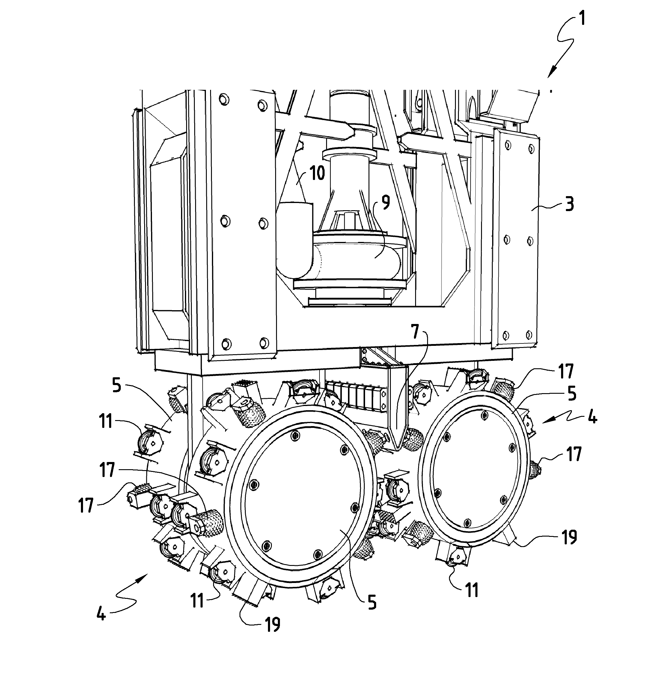
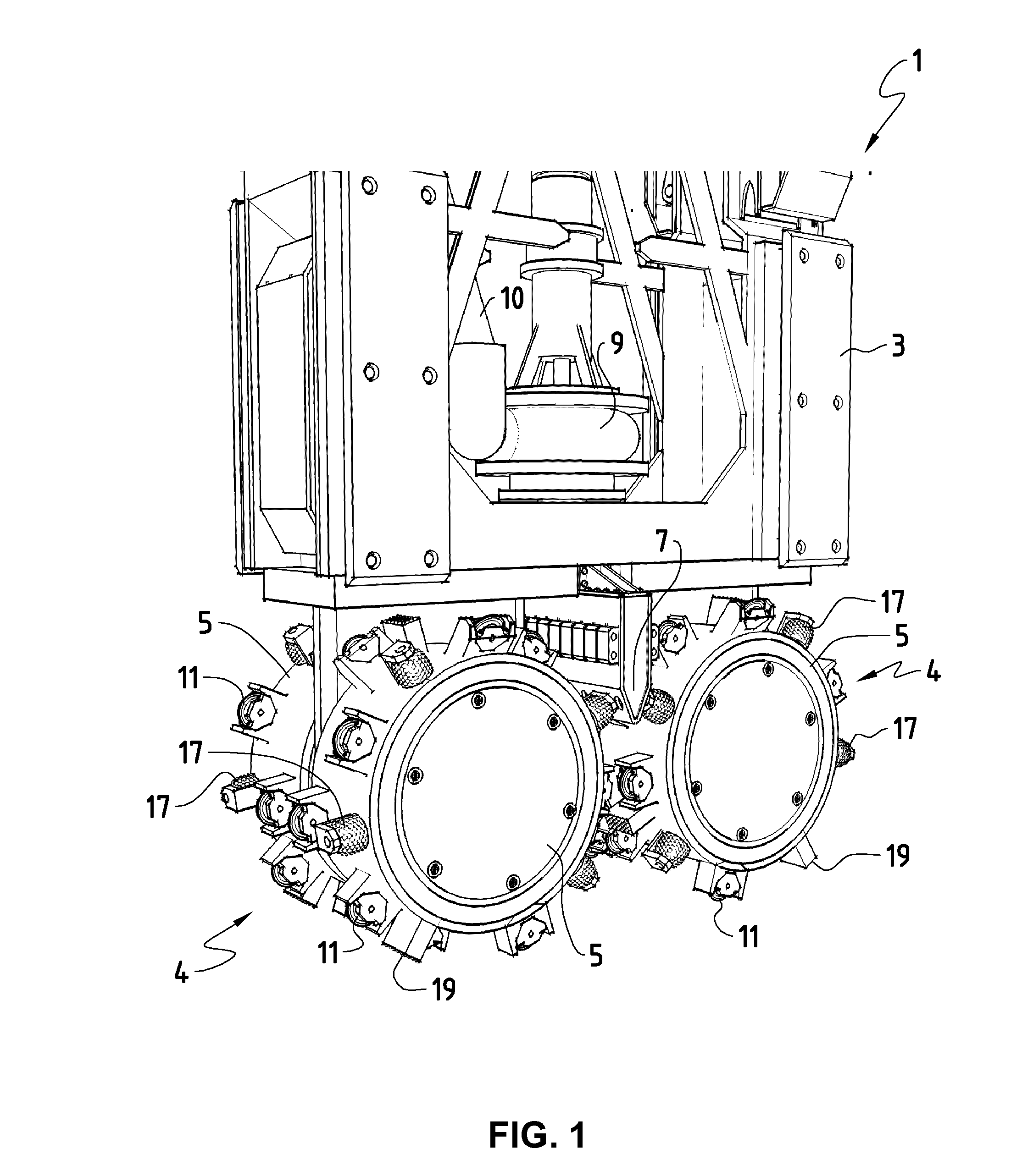
[0025]FIG. 1 illustrates in a perspective front view the lower end of a hydromill 1 suitable for excavating for instance trenches in a hard rock. The upper end of the hydromill 1 is not shown, and also elements external to the hydromill itself, such as the crane, are omitted in the following description. These external elements are not important to understand the teachings of the present invention. A hydromill frame 3 forms the top part of the hydromill 1, while wheels 4 form the bottom part of the hydromill 1. The system 1 has two wheel pairs, i.e. altogether four wheels 4. The wheels 4 of one pair can be considered to rotate around the same rotational axis A, B, shown in FIGS. 4 and 5.

[0026]A motor (not shown) for rotating t...


PUM


Abstract

The present invention concerns a hydromill wheel (5) for excavating a trench in hard rock. The wheel comprises a drum (4) arranged to be rotated about its axis (A, B). The wheel (4) further comprises a plurality of single disc cutters (11) mounted on the periphery of the drum (5), the single disc cutter (11) having a rotatable single cutting disc (11) arranged to come in contact with and crush the rock during excavation. The spacing of the projection of at least some of the cutting discs (11) on the drum axis (A, B) is 20% to 70% of the cutting disc diameter.

Description

TECHNICAL FIELD[0001]The present invention relates to hydromills suitable for excavating trenches in hard or very hard rock. The invention also relates to a corresponding hydromill wheel and to a method of excavating by using the hydromill.BACKGROUND OF THE INVENTION[0002]Trench cutters, also known as hydromills under their generic name, are used in foundation engineering processes, for instance to build diaphragm walls. Trench cutter systems comprise generally a frame, such as a steel frame, that can be lowered into the ground that is being excavated. Normally a motor and two cutter wheel pairs, which are arranged to be rotated by the engine, are installed at the end of the frame that is to be first lowered in the ground. Each wheel pair has a first wheel and a second wheel arranged so that one engine is arranged inside these two wheels or drums. The cutter can be lowered vertically under continuous rotation of the cutter wheels, and depths of more than 150 m can be reached. The ad...

Claims


Application Information

Patent Timeline
Patent Type & Authority Applications(United States)
IPC IPC(8): E02F3/20E02F3/24E02F5/08
CPCE02F3/20E02F3/205E02F3/241E02F5/08E02F3/245E02F3/9237E21B10/50
Inventor GILLARD, JEAN-CHRISTOPHE
Owner VSL INT AG
Why Eureka
Try Eureka