Protective circuit

a protection circuit and circuit technology, applied in the field of protective circuits, can solve problems such as damage, electrical load damage, and insufficient voltage supply to electrical load, and achieve the effects of reducing the risk of electrical load damag

Inactive Publication Date: 2015-11-12
ROBERT BOSCH GMBH
View PDF12 Cites 2 Cited by
  • Summary
  • Abstract
  • Description
  • Claims
  • Application Information

AI Technical Summary

Benefits of technology

[0010]The buffer capacitor is able to allow an after-run of the electrical load when the voltage at the input of the protective circuit is interrupted or temporarily has a smaller value than the voltage of the buffer capacitor. The electrical load is thereby able to remain operative at least for a short time, even if no electric energy is able to be drawn from the motor-vehicle electrical system. For example,

Problems solved by technology

If a polarity reversal happens in this context, the electrical load may suffer damage.
In addition, a high current may flow, which in the simplest case, may trigger a fuse in the direct voltage system, and in the most unfavorable case, may cause damage owing to excess current at the load or in the motor-vehicle electrical system.
The disadvantage in doing this is that a customary free-wheeling diode exhibits significant reverse voltage, so that in some cir

Method used


Image

  • Protective circuit
  • Protective circuit

Examples


Embodiment Construction

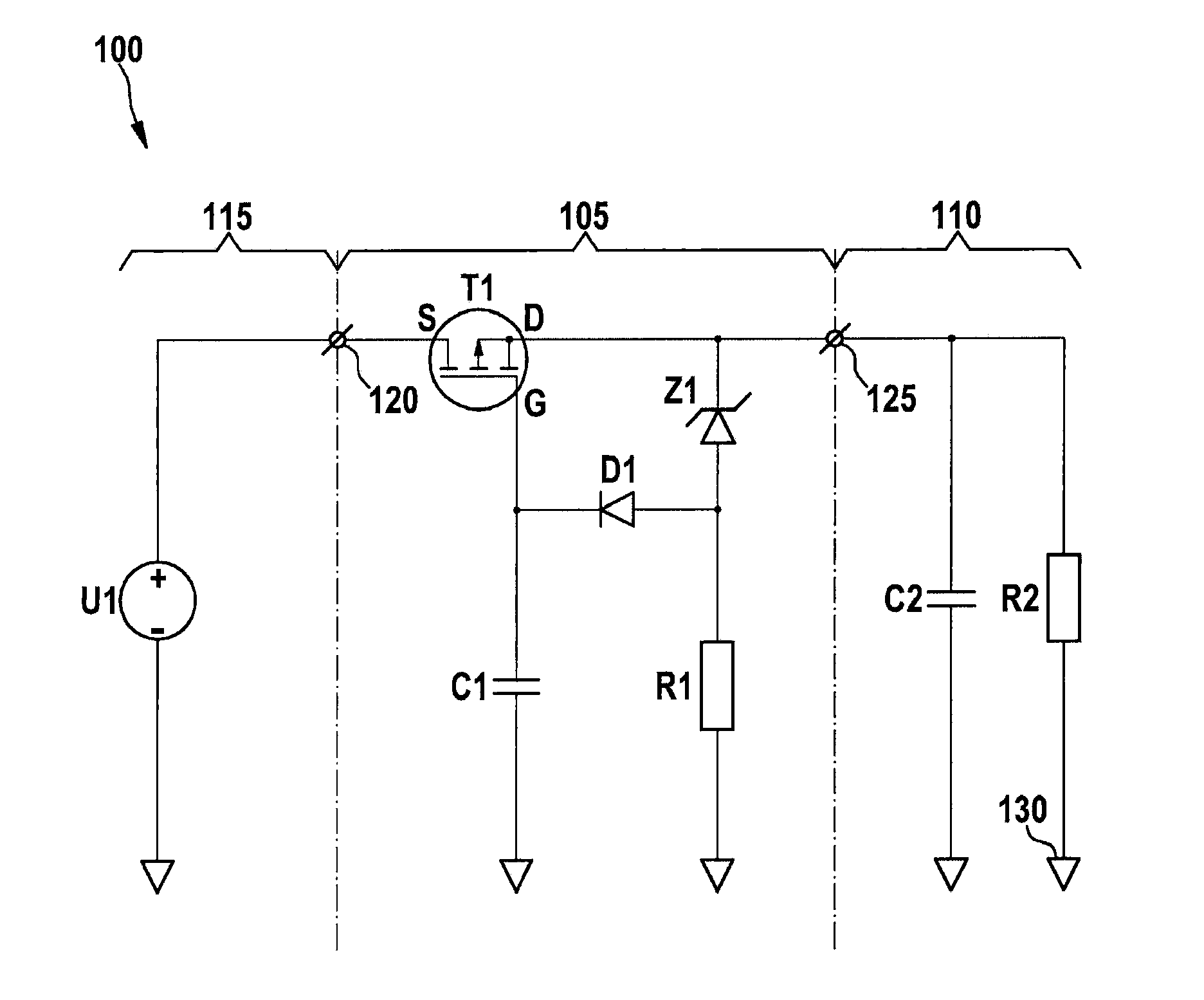
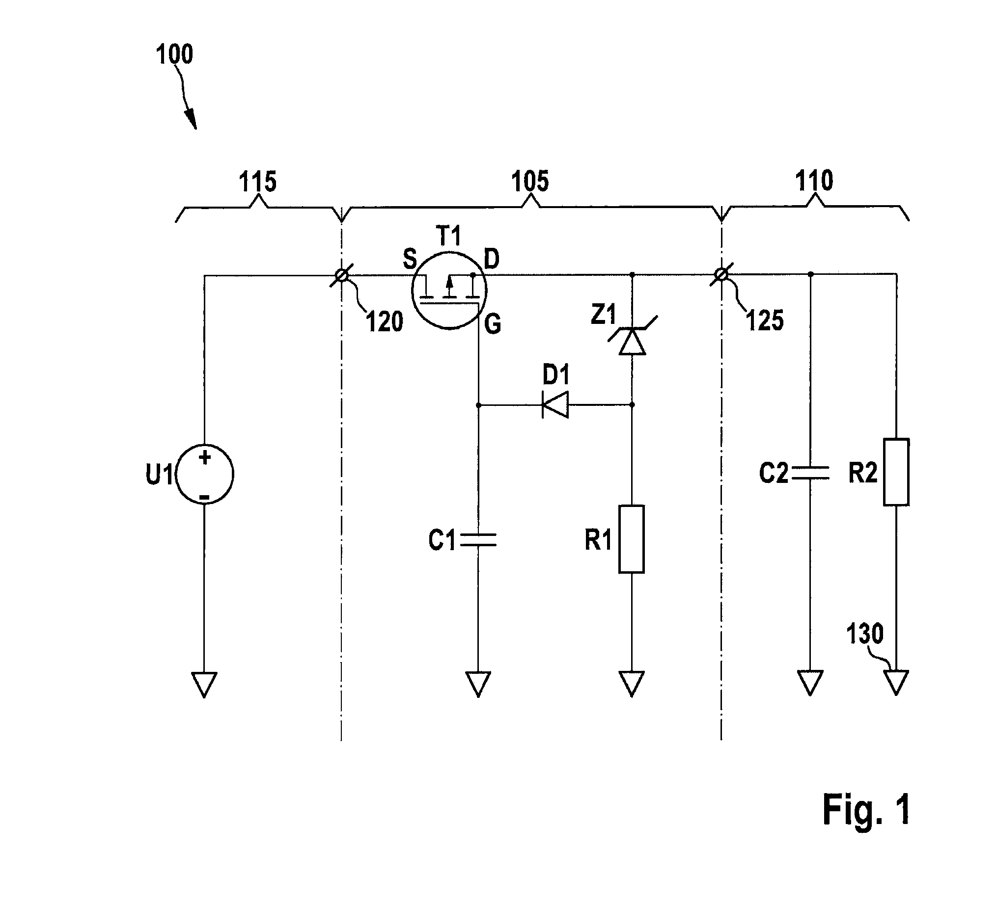
[0014]The FIGURE shows a system 100 on board a motor vehicle. System 100 includes a protective circuit 105 in order to operate a load 110 on an on-board voltage network 115. On-board voltage network 115 preferably makes a direct voltage available having a nominal value in the area of 12 V, 24 V, 36 V or 48 V. A possible residual ripple of the direct voltage of on-board voltage network 115 may be disregarded in the context given.

[0015]Electrical load 110 may be modeled as an ohmic load having a resistor R2. In one specific embodiment, connected in parallel to ohmic resistor R2 is a buffer capacitor C2 that allows operation of electrical load 110 when no electric current is flowing to electrical load 110 from on-board voltage network 115.

[0016]Protective circuit 105 includes a field-effect transistor T1, a Zener diode Z1, a diode D1, a resistor R1, an input 120 and an output 125. Hereinafter, it is assumed that on-board voltage network 115 is conducting a voltage U1.

[0017]Field-effect...


PUM


Abstract

A protective circuit includes an input, an output, a p-type field-effect transistor whose drain terminal is connected to the input and whose source terminal is connected to the output, a capacitor between the gate terminal of the field-effect transistor and ground, a Zener diode whose cathode is connected to the output, a resistor between the anode of the Zener diode and ground, and a diode whose anode is connected to the anode of the Zener diode and whose cathode is connected to the gate terminal of the field-effect transistor.

Description

FIELD OF THE INVENTION [0001]The present invention relates to a protective circuit. In particular, the invention relates to a protective circuit for operating an electrical load on board a motor vehicle.BACKGROUND INFORMATION [0002]Usually a direct voltage system is used for the power supply of electrical loads on board a motor vehicle. A nominal voltage of such a direct voltage system normally lies at 12 V in an automobile or 24 V in a truck. As a rule, an electrical load is connected between a supply connection and ground to the vehicle electrical system, the electrical ground and the vehicle ground being able to be equated. If a polarity reversal happens in this context, the electrical load may suffer damage. In addition, a high current may flow, which in the simplest case, may trigger a fuse in the direct voltage system, and in the most unfavorable case, may cause damage owing to excess current at the load or in the motor-vehicle electrical system. Therefore, especially in order...

Claims


Application Information

Patent Timeline
IPC IPC(8): H02H3/10H02H3/00
CPCH02H3/003H02H3/10H02H3/18H02H11/003
Inventor KOSTORZ, WOLFGANG
Owner ROBERT BOSCH GMBH
Why Eureka
Try Eureka