Mechanical converter assembly and implementations

a technology of mechanical converters and components, applied in the field of mechanical converter assembly and implementation, can solve the problems of limiting the ability to perform useful operations with a conventional hand tool, and affecting the use of conventional hand tools

Active Publication Date: 2015-11-19
GYRUS ACMI INC (D B A OLYMPUS SURGICAL TECH AMERICA)
View PDF5 Cites 0 Cited by
  • Summary
  • Abstract
  • Description
  • Claims
  • Application Information

AI Technical Summary

Benefits of technology

[0086]In a manner as previously discussed, application of mechanical drive signal 646 to input transfer element 605 as shown in FIG. 6B causes the respective levers in mechanical converter assembly 620 to advance the output element 606 through space 655. As previously discussed, the mechanical converter assembly 620 provides translational gain along a respective axis. Eventually, based on application of a force to input element 605, the output element 606 moves and strikes the element 670, causing the shaft 625 (and element 670) of hand tool 610 to move along axis 115 away from mechanical converter assembly 620. Movement of the output element 606 through the space 655 ensures that a sufficient amount of gathered momentum is transferred from input element 605 and corresponding levers to the element 670 and shaft 625, causing a combination of the element 670 and shaft 625 to move to the right as shown in FIG. 6B (with respect to FIG. 6A).

Problems solved by technology

Conventional techniques of providing translational motion in a tool suffer from deficiencies.
However, the amount of translational movement provided by the piezoelectric stack may be limited.
Thus, the ability to perform useful operations with a conventional hand tool may be limiting because of the inability to provide a proper stroke length.

Method used


Image

  • Mechanical converter assembly and implementations
  • Mechanical converter assembly and implementations
  • Mechanical converter assembly and implementations

Examples


Embodiment Construction

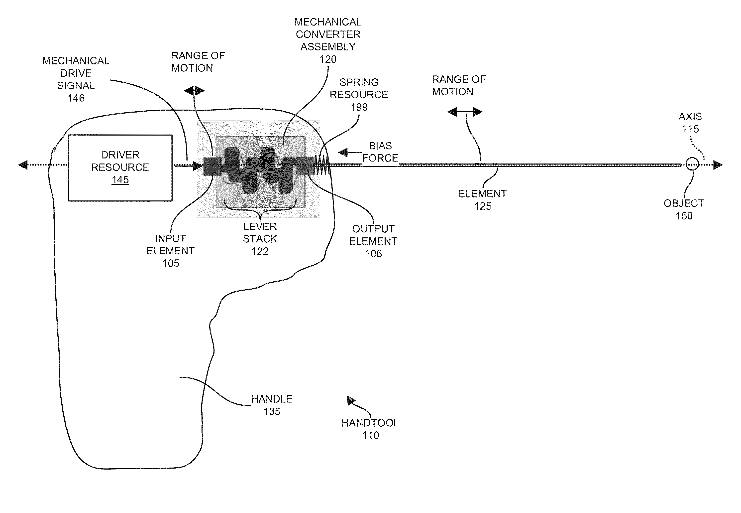
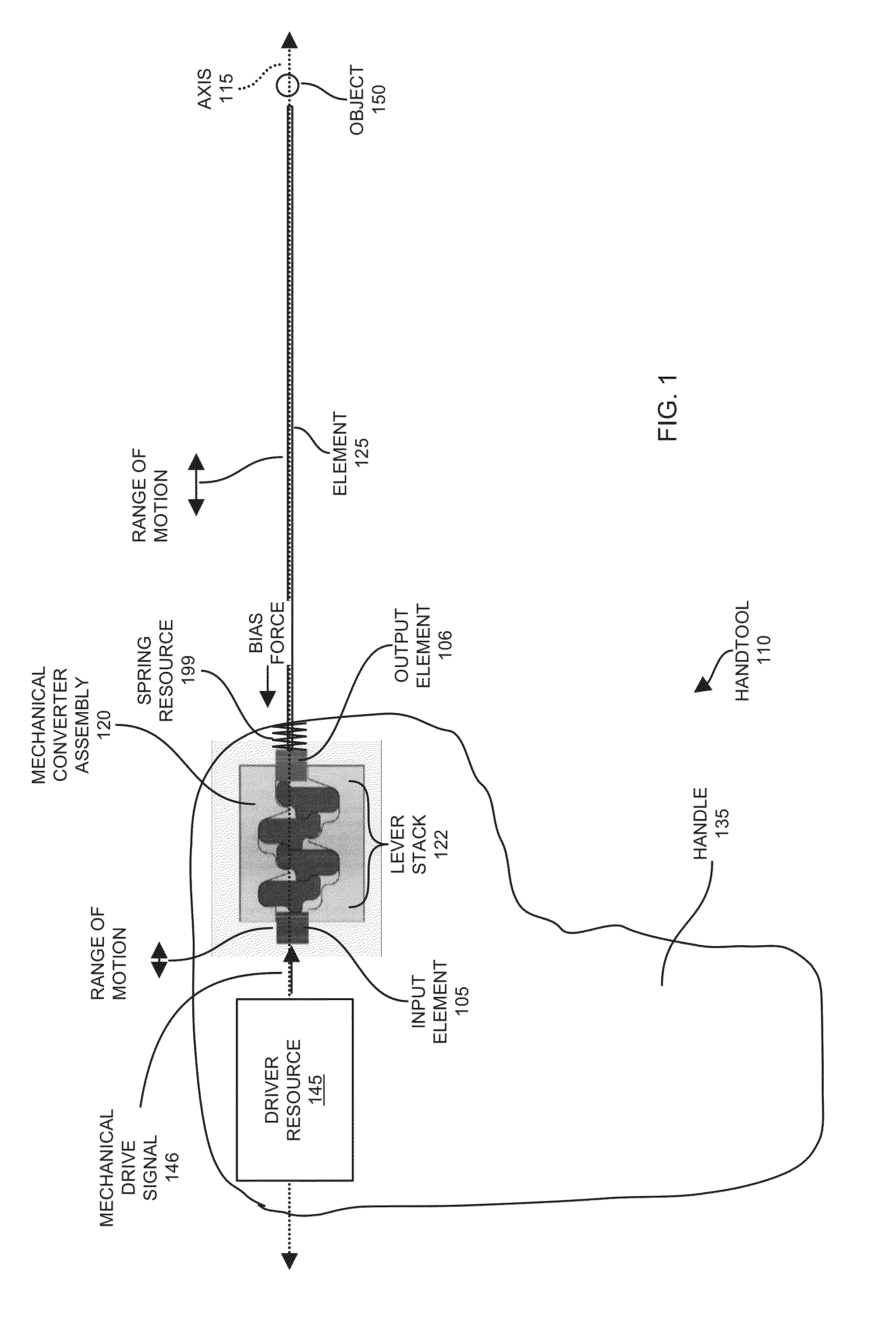
[0040]Now, more specifically, FIG. 1 is an example diagram of a hand tool including a mechanical converter assembly according to embodiments herein.

[0041]As shown, hand tool 110 includes handle 135, driver resource 145, mechanical converter assembly 120, and element 125.

[0042]In general, during operation, driver resource 145 produces mechanical drive signal 146. Input element 105 at the input of mechanical converter assembly 120 receives mechanical drive signal 146. Via lever stack 122 (including multiple levers), the mechanical converter assembly 120 converts received mechanical drive signal 146 (such as a mechanical drive force) into a respective mechanical output signal (or output drive force) that is outputted from the mechanical converter assembly 120 at the output element 106.

[0043]In one embodiment, the driver resource 145 produces a translational motion that is inputted to input element 125 of mechanical converter assembly 120. Mechanical converter assembly 120 converts the ...


PUM


Abstract

A mechanical converter assembly includes an input, a lever stack (multiple levers), and an output. The input is configured to receive a mechanical drive force (or mechanical input signal) from a driver resource. The lever stack translates the received drive force into a mechanical output force (or mechanical output signal). The output of the mechanical converter assembly is configured to apply the mechanical output force produced by the lever stack to a driven element. In one embodiment, use of the lever stack in the mechanical converter assembly provides translational gain in which an amount of translational movement at the input of the mechanical converter assembly results in a substantially greater amount of corresponding translational movement at the output.

Description

RELATED APPLICATIONS[0001]This application is related to and claims the benefit of earlier filed United States Provisional Patent Application Ser. No. 61 / 992,259 entitled “MECHANICAL CONVERTER ASSEMBLY AND IMPLEMENTATIONS,” (Attorney Docket No. OLM14-03(G0158-US1)P), filed on May 13, 2014, the entire teachings of which are incorporated herein by this reference.BACKGROUND[0002]Ultrasonic and pneumatic lithotripsy or so-called stone-breaking devices have been available for medical use for a number of decades. Currently, there exist a number of rigid solid tubular shaft-based lithotripsy devices that use ultrasonic or pneumatic energy to break a respective stone down into smaller pieces for easier removal from a respective patient's urologic system.[0003]In general, during use of a shaft-based lithotripsy device, ultrasonic acoustic frequency energy is transmitted (translated) down a stiff metal shaft and delivered by contact to a kidney stone. The tips of tubes or shafts in such devic...

Claims


Application Information

Patent Timeline
Patent Type & Authority Applications(United States)
IPC IPC(8): A61B17/22
CPCA61B17/22004A61B17/22012F16H25/183A61B2017/22015
Inventor ST. GEORGE, LAWRENCE J.
Owner GYRUS ACMI INC (D B A OLYMPUS SURGICAL TECH AMERICA)
Why Eureka
Try Eureka