Coiled tubing lap welds by magnetic pulse welding

a magnetic pulse welding and lap welding technology, applied in the field of joining tubing, can solve the problems of difficulty in successfully delivering ct through its full length, inability to achieve, and large time savings, and achieve the effect of high strength ct joint and little or no loss of ct integrity

Inactive Publication Date: 2015-11-19
CONOCOPHILLIPS CO
View PDF13 Cites 17 Cited by
  • Summary
  • Abstract
  • Description
  • Claims
  • Application Information

AI Technical Summary

Benefits of technology

[0015]The invention more particularly includes using Electromagnetic Pulse Technology (EMPT) to provide a high strength CT joint. Because the joint strength is equal to the strength of the work piece, there will be little or no loss of CT integrity when using EMPT to weld CT. In addition EMPT welding can produce helium-tight connections of different metallic materials without creating a heat affected zone. Stainless steels, which are often difficult to weld by fusion welding, can be welded by EMPT and even dissimilar welds between steel and aluminum, steel and copper, as well as copper and aluminum are feasible.

Problems solved by technology

As the measured depth of a well increases so does the difficulty level of successfully delivering CT through its full length.
However, as CT is a continuous spool of rugged tubing its deployment into a well offers a considerable time savings as compared to jointed pipe alternatives.
Another benefit of CT over jointed pipe alternatives is that when using CT a continuous flow of fluid can be pumped through the tubing, whereas this is not possible with jointed pipe deployments.
However, some issues have arisen with the use of CT.
Even using a bias weld, CT will often fail at these bias welds.
Another issue that has arisen with CT involves the length of tubing that may be placed on a single reel.
It is apparent that the largest diameter reel may not hold the length of tubing that may be needed for use in deeper wells.
Not surprisingly, the fatigue endurance of CT can be affected by the presence of defects, which occur regularly in harsh oilfield environments.
However, when the CT is damaged, it is difficult to repair.
Unfortunately, joints on the round, or potentially oval, CT are more complicated to make and typically less reliable than when originally manufactured.
Unfortunately the repair strength does not typically meet requirements to continue use of the CT and once removed from the wellbore, the CT cannot be reused if the tubing has been repaired.
Even the best butt-welded joint may not last for more than half of the coiled tubes' rated fatigue life.
This is because basic tensile and hoop stress properties may be compromised.
Welding different reels of CT together is not desirable at the manufacturer location or the field location since the weld may not be biased, resulting in a substantial loss of that joints fatigue life and tensile strength.
The problems with CT therefore include difficulty in repairing existing tubing that is already coiled, and difficulty in joining multiple coils together.

Method used


Image

  • Coiled tubing lap welds by magnetic pulse welding
  • Coiled tubing lap welds by magnetic pulse welding
  • Coiled tubing lap welds by magnetic pulse welding

Examples


example 1

EMPT Tubing Expansion

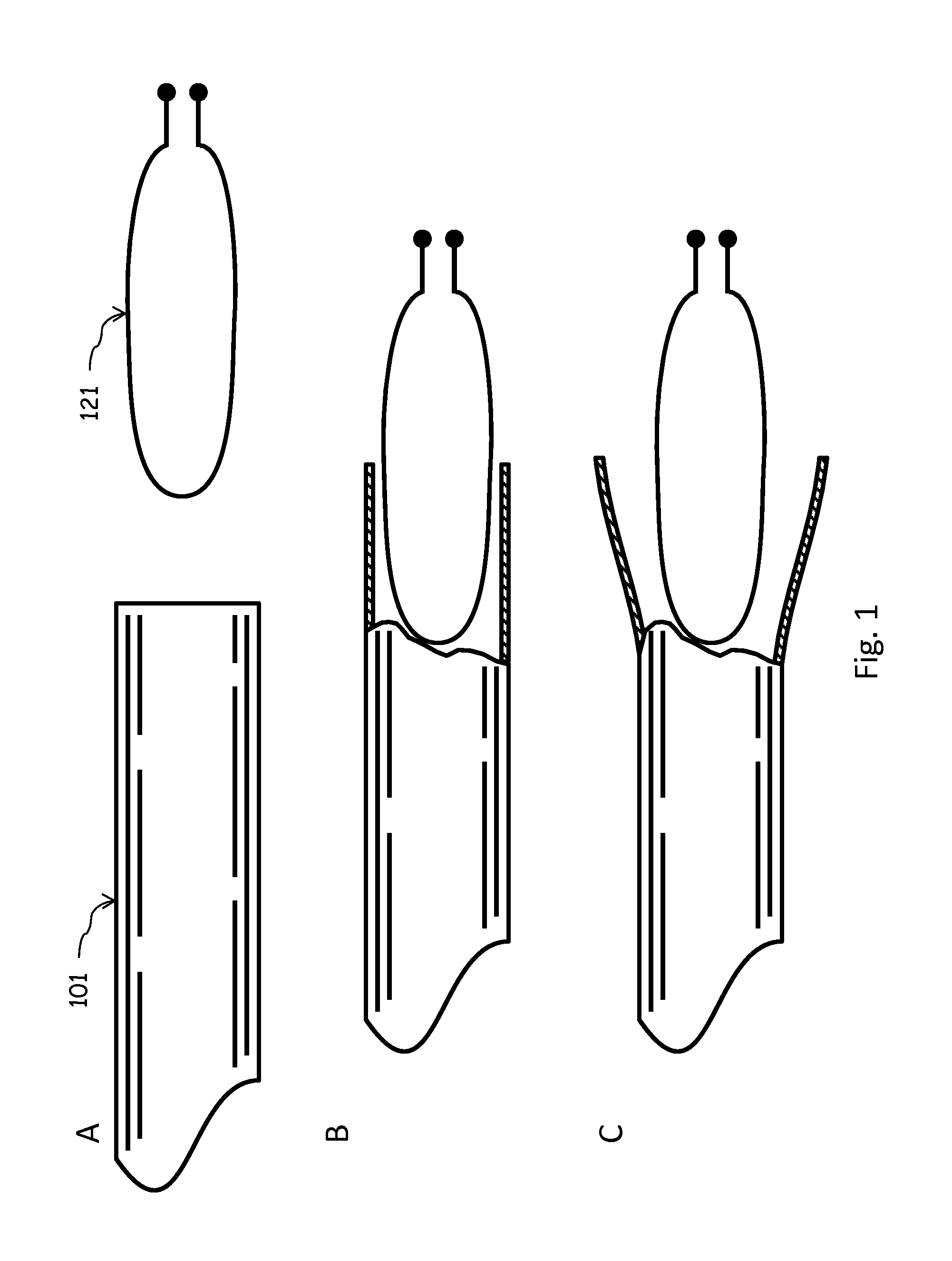
[0039]Coiled tubing is expanded to where the inside diameter of the expanded tubing is greater than the outside diameter of the complementary tubing end. In one embodiment a damaged section of tubing is identified and removed. In another embodiment, one end of a CT is to be joined with an existing CT. The CT end is inspected, if the tubing is too thin, misshapen, cracked or damaged, the piece may be cut back. The end piece may be cut flat and or cleaned of burrs, dirt, and anomalies. Once the end is ready to be expanded an expansion coil 121 is inserted into the coiled tubing 101. A pulsed energy source is transmitted through the expansion coil 121 causing the coiled tubing 101 to expand as shown in FIG. 1. Optionally a mandrel, casing, or die may be placed around the CT to obtain a specific geometric shape or diameter of expansion. If the CT has insufficient conductivity, it may cause ohmic losses and heating. To overcome this a driver, i.e. thin walled copper,...

example 2

Conventional Tubing Reaming

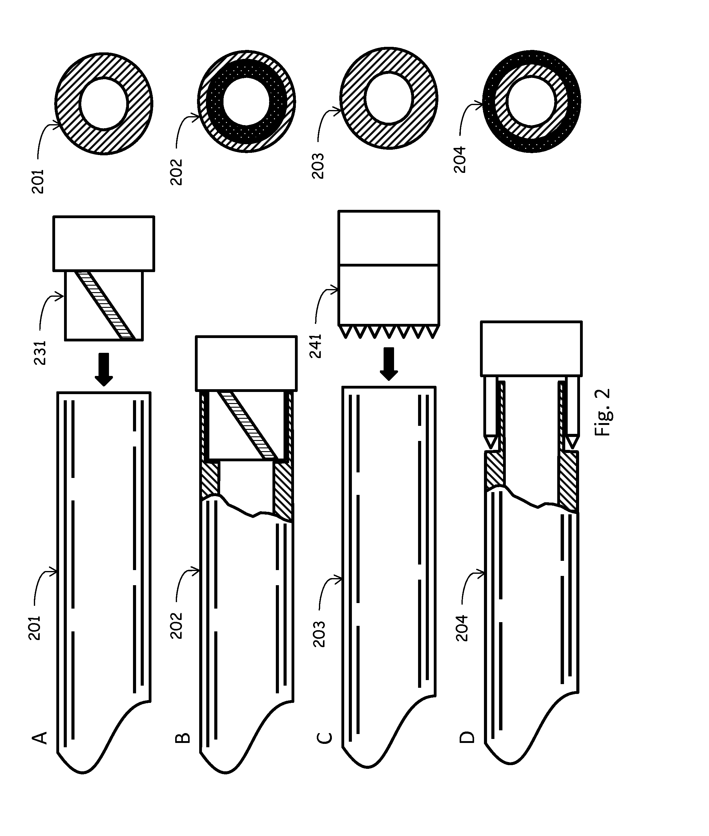
[0040]CT is reamed to create a male and female end as shown in FIG. 2. One simple method for reaming involves using a press to insert a reaming bit internally 231 or externally 241. The reaming bit has an exact diameter internally and externally ensuring that the reamed female end will fit tightly over the reamed male end. There may be additional clamps, vices and guides in place to ensure the reaming is centered and that the two ends are complementary to very high tolerances. After reamed, the female end 202 has an outside wall and the internal surface is cut away. The male end 204 has an inside wall and the outside surface is cut away. The cut away section is depicted as black area in the end view.

[0041]CT may be reamed to create overlapping ends of various geometries as shown in FIG. 3. This may be done with shaped bits or with a rotating die that is placed over the end of the tubing. FIG. 3A depicts complementary female 301 and male 302 ends that are n...

example 3

MPW with Expanded Tubing

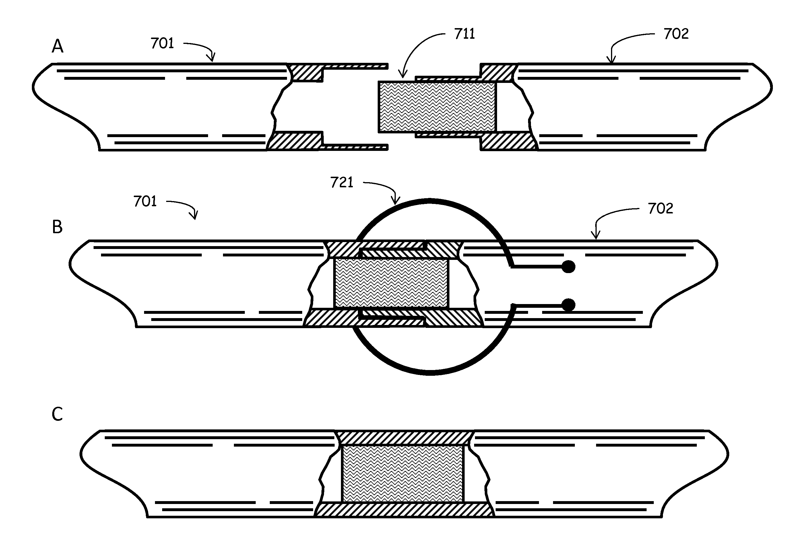
[0042]Expanded tubing may be joined to standard CT to create a continuous piece of CT with no disruption to the internal diameter of the tubing as shown in FIG. 4. A cleaned CT end 401 is placed in an expanded tubing end 402. The MPW compression coil 421 is used to compress the expanded tubing onto the CT end creating a continuous piece of CT. Because the MPW retains the strength of the bonded materials, this weld will not decrease the tubing quality and may be used on tubing as it is being placed downhole.


PUM

PropertyMeasurementUnit
diameteraaaaaaaaaa
diameteraaaaaaaaaa
yield strengthsaaaaaaaaaa

Abstract

A method for joining coiled tubing is described. Coiled tubing joints using a magnetic pulse welder are described that retain the strength of the original tubing. This type of joint is useful for joining multiple coiled tubing sections or for removing and repairing damaged coiled tubing. Because the joint is as strong as the original tubing, these types of joints may be used when placing tubing in the well.

Description

CROSS-REFERENCE TO RELATED APPLICATIONS[0001]This application is a non-provisional application which claims benefit under 35 USC §119(e) to U.S. Provisional Application Ser. No. 62 / 000,363 filed May 19, 2014, entitled “COILED TUBING LAP WELDS BY MAGNETIC PULSE WELDING,” which is incorporated herein in its entirety.STATEMENT REGARDING FEDERALLY SPONSORED RESEARCH[0002]None.FIELD OF THE INVENTION[0003]The present invention relates generally to joining tubing for the production of hydrocarbons from a subterranean reservoir. More particularly, but not by way of limitation, embodiments of the present invention include lap welding two separate pieces of coiled tubing using magnetic pulse welding.BACKGROUND OF THE INVENTION[0004]Coiled tubing is a means of conveyance of fluid in an oilfield, and its value is attributed to the coiled tubing being continuous, rugged, and suitably stiff. Coiled Tubing (CT) has been defined as any continuously-milled tubular product manufactured in lengths tha...

Claims


Application Information

Patent Timeline
Patent Type & Authority Applications(United States)
IPC IPC(8): B23K13/02B23K35/00B23K20/06
CPCB23K13/025B23K35/00B23K20/06B23K2101/10
Inventor GRUBB, SCOTT A.
Owner CONOCOPHILLIPS CO
Why Eureka
Try Eureka