Method for diagnosing a fuel tank vent valve

Active Publication Date: 2015-11-19
ROBERT BOSCH GMBH
View PDF4 Cites 0 Cited by
  • Summary
  • Abstract
  • Description
  • Claims
  • Application Information

AI Technical Summary

Benefits of technology

The present invention provides a method for diagnosing a fuel tank vent valve in a motor vehicle to quickly detect defects after start-up of the engine. This is achieved by analyzing a curve of pressure over time in a sub-chamber of the vehicle, which contains the fuel tank and other components. This method is simple and can be easily integrated into existing electronic control units without requiring any changes. It allows for the identification of defective fuel tank vent valves during driving cycles, ensuring timely maintenance and preventive measures.

Problems solved by technology

However, since these activated carbon filters cannot adsorb and store an infinite quantity of fuel vapors, it is necessary to empty or regenerate the filters.
This could lead to the correctly functioning components being incorrectly identified as defective.
If the fuel tank vent valve is jammed open and the engine is started, due to the system this always results in a pressure drop in the sub-chamber.
Since the fuel tank vent valve is always closed in the absence of any flow, this pressure drop may moreover only be caused by a jammed-open fuel tank vent valve.

Method used


Image

  • Method for diagnosing a fuel tank vent valve
  • Method for diagnosing a fuel tank vent valve
  • Method for diagnosing a fuel tank vent valve

Examples


Embodiment Construction

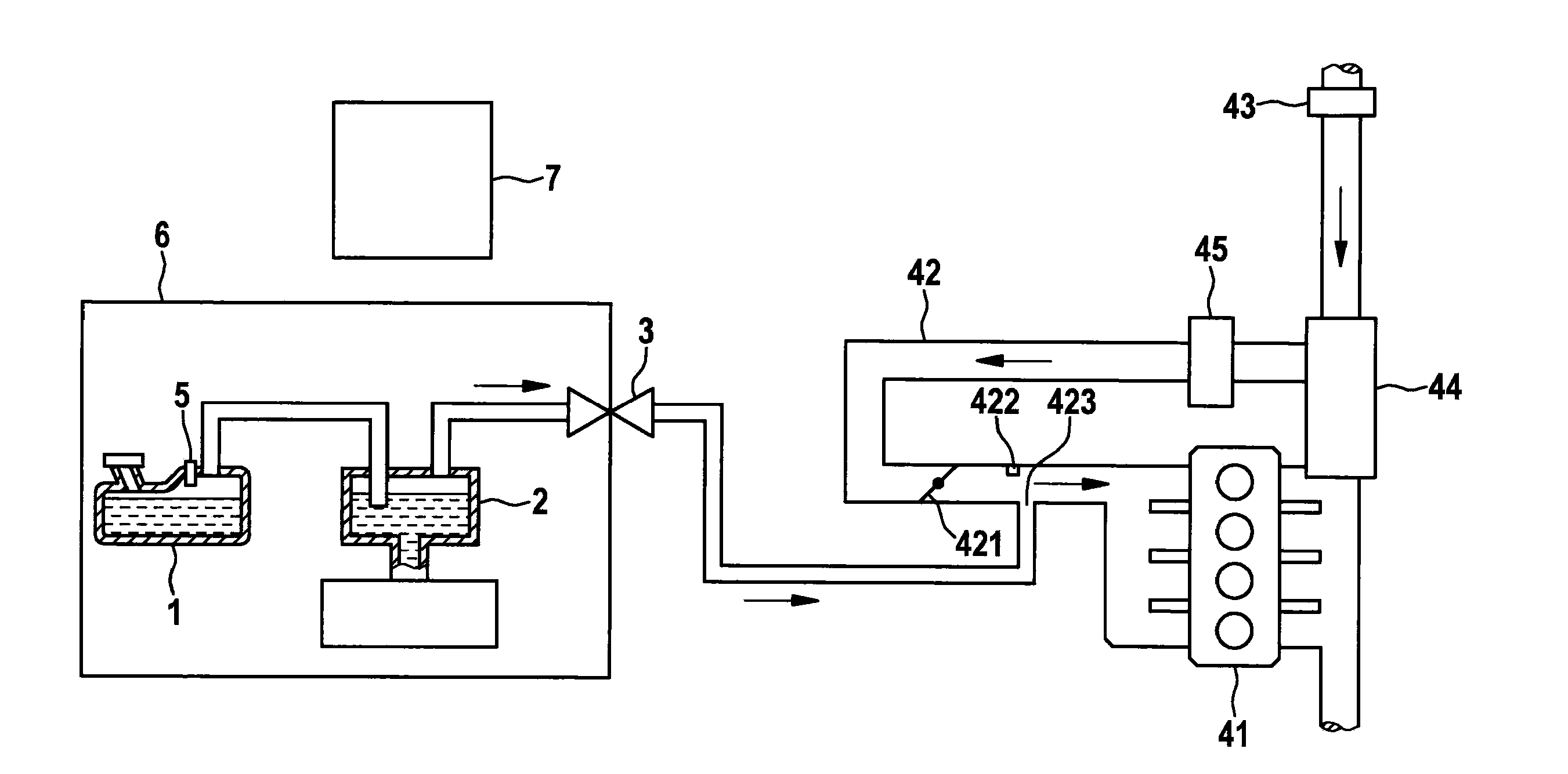
[0014]FIG. 1 shows a conventional fuel tank venting system of a motor vehicle. A fuel tank 1 is connected to an activated carbon filter 2. A line leads from activated carbon filter 2 to fuel tank vent valve 3. A line leads from fuel tank vent valve 3 to an intake manifold 42 of an internal combustion engine 41. Ambient air is transported into a turbocharger 44 through an air filter 43. From there, it is further conveyed through a charge air cooler 45 into intake manifold 42. A throttle valve 421 and an intake manifold pressure sensor 422 are situated in the intake manifold. The intake manifold is connected to internal combustion engine 41. Pressure sensor 5 is situated in fuel tank 1. This pressure sensor 5 measures pressure p in sub-chamber 6 of the motor vehicle, which contains fuel tank 1, activated carbon filter 2, line 11 which connects fuel tank 1 to activated carbon filter 2, and line 21 which connects activated carbon filter 2 to fuel tank vent valve 3. The illustrated compo...


PUM


Abstract

A method for diagnosing a fuel tank vent valve of a motor vehicle. In the method it is inferred, from a curve of a pressure p over time in a sub-chamber of the motor vehicle after a start-up of an internal combustion engine of the motor vehicle, as to whether the fuel tank vent valve is jammed open. The sub-chamber contains a fuel tank of the motor vehicle and is delimited by the fuel tank vent valve.

Description

FIELD OF THE INVENTION[0001]The present invention relates to a method for diagnosing a fuel tank vent valve of a motor vehicle. The present invention also relates to a computer program which is designed to carry out each step of the method according to the present invention, and to a machine-readable storage medium on which the computer program according to the present invention is stored. Finally, the present invention relates to an electronic control unit which is designed to carry out a diagnosis of a fuel tank vent valve of a motor vehicle with the aid of the method according to the present invention.BACKGROUND INFORMATION[0002]In order to protect the environment, vapors which become separated from fuels in the fuel tank of a motor vehicle must not enter the environment. In order to prevent this from happening, motor vehicles are equipped with an activated carbon filter (ACF) which is intended to adsorb these vapors. However, since these activated carbon filters cannot adsorb an...

Claims


Application Information

Patent Timeline
IPC IPC(8): B60K15/035
CPCB60K2015/03328B60K15/03519
Inventor MEINKEN, ANDREASBRUESTLE, SIMONWIECZOREK, THOMASKASTNER, JOHANNESDEIBELE, BERNHARD
Owner ROBERT BOSCH GMBH
Why Eureka
Try Eureka