
Diagnostic System and Method for Testing Integrity of Stack During Ultrasonic Welding

a technology of ultrasonic welding and integrity testing, applied in the direction of mechanical vibration separation, instruments, conductors, etc., can solve the problems of discarded parts, substandard welds, and inferior welds that do not meet established criteria for a desired application

Active Publication Date: 2015-11-19
SONICS & MATERIALS
View PDF5 Cites 9 Cited by
  • Summary
  • Abstract
  • Description
  • Claims
  • Application Information

AI Technical Summary

Benefits of technology

The invention is about a way to test the integrity of a stack during ultrasonic welding. The method involves measuring the vibrations of the welding equipment during the welding process and comparing it to a standard profile to determine any errors or differences. The system includes a controller and a power source, and the method can be easily executed by a senior R&D personnel. Overall, the invention provides a more accurate and efficient way to verify the quality of ultrasonic welds.

Problems solved by technology

A disadvantage of such systems is that if insufficient energy is transmitted to the parts being welded via the vibrations of the horn, it can result in an inferior weld that does not meet established criteria for a desired application.
Another disadvantage of such systems is that any defect with the power supply or the stack can result in insufficient energy being used to form the weld, resulting in a substandard weld.
In some cases, the poor quality of the weld is evident upon inspection and the part is discarded.
A disadvantage with diagnosing such systems is that it is difficult to determine whether the substandard weld is a result of a problem with the power supply, the stack, or both.
This disadvantage can result in significant, and costly, downtime to diagnose and correct the problem.
The stack is typically a complex and precise instrument and, therefore, it is time consuming and difficult to identify and correct errors associated therewith.
As a result, there is a tendency to attribute poor quality welds to errors with the power source instead of the stack, even when the power source is operating according the specification.
This can result in incurring unnecessary costs to repair or replace the power source.
Another disadvantage of such ultrasonic welding systems is that in some cases, a problem with the stack results in a substandard weld, albeit one that is not perceptible to operator of the system.

Method used


Image

  • Diagnostic System and Method for Testing Integrity of Stack During Ultrasonic Welding
  • Diagnostic System and Method for Testing Integrity of Stack During Ultrasonic Welding
  • Diagnostic System and Method for Testing Integrity of Stack During Ultrasonic Welding

Examples


Embodiment Construction

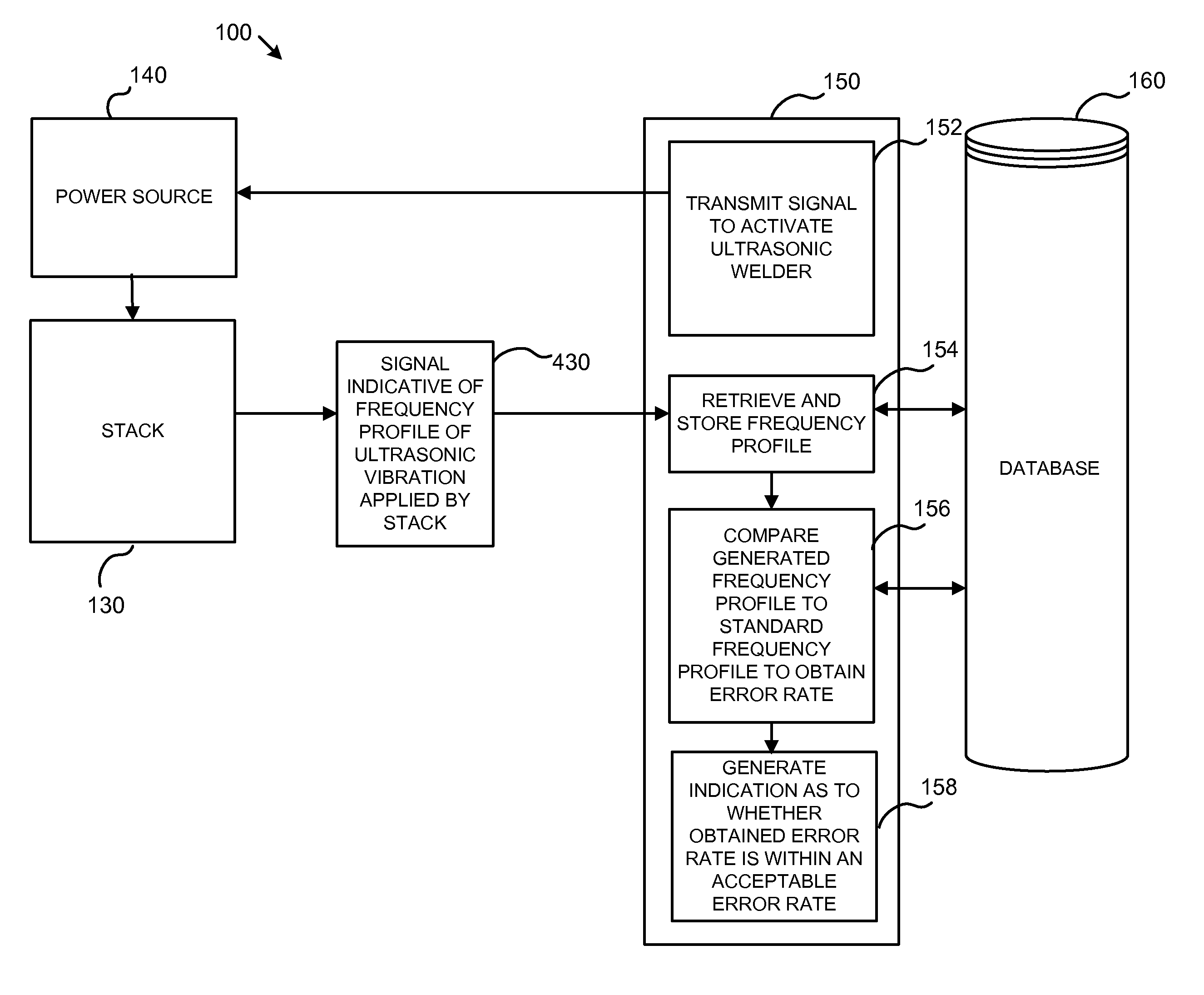
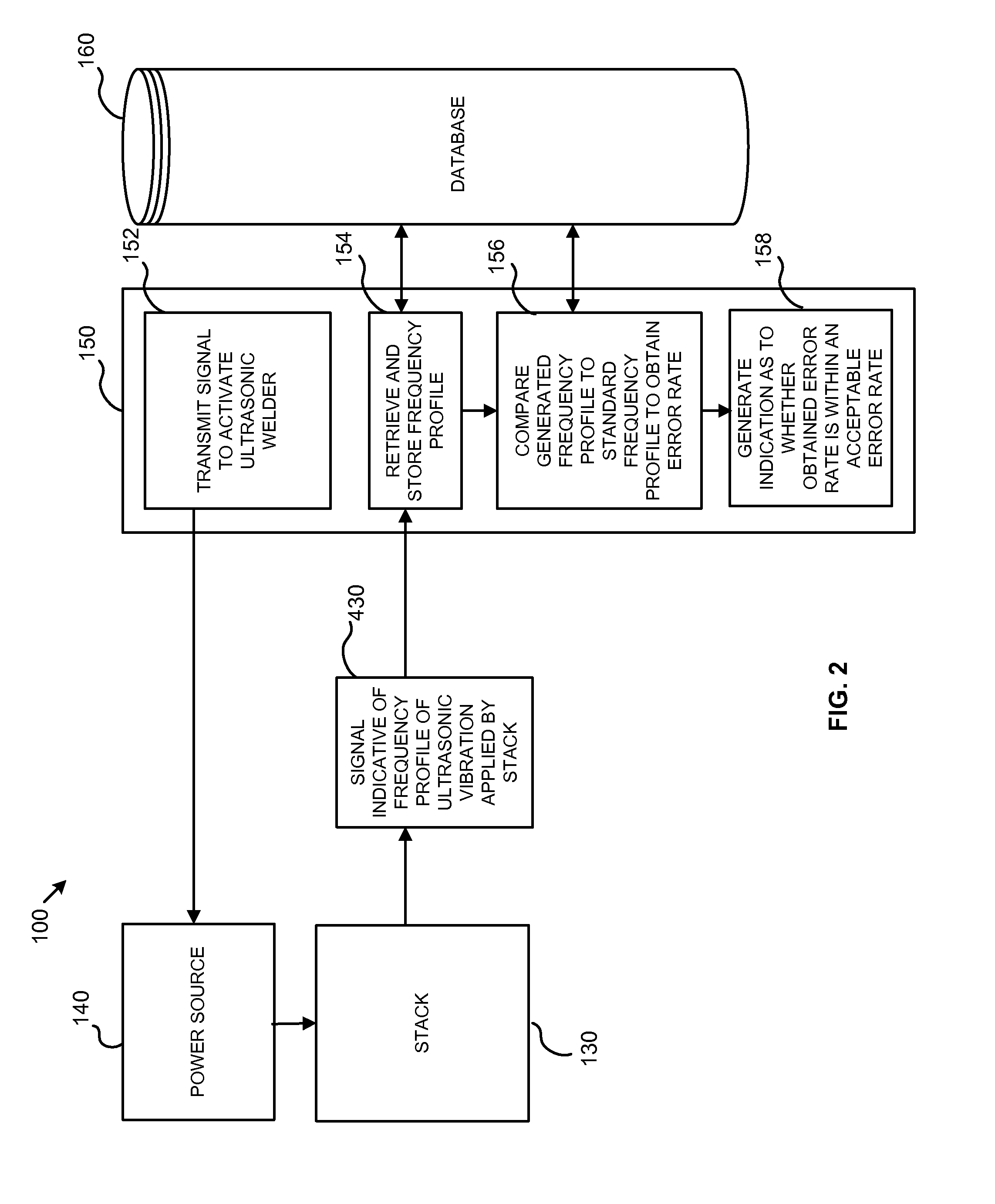
[0022]The inventors have discovered new methods and systems that overcome many of the problems associated with the prior art. Specifically, the inventors have discovered a method and system for testing the integrity of a stack during ultrasonic welding by comparing a measured frequency profile of the horn during an ultrasonic weld with a standard frequency profile for the horn.

[0023]In reference to FIG. 2, a system 100 in accordance with one embodiment of the present is shown. The system 100 includes a controller 150. The controller 150 may be, for example, a standard processor based computer system having software executing thereon and a data storage associated therewith. Such generic controllers are known in the art, for example, the “WSC Controller” manufactured by Sonics & Materials, Inc. of Newtown, Conn. The “WSC Controller” includes a power source integrated therein, however, a person of ordinary skill in the art will understand that the power source and the controller may be...


PUM

PropertyMeasurementUnit
Timeaaaaaaaaaa
Frequencyaaaaaaaaaa
Erroraaaaaaaaaa

Abstract

A method for testing the integrity of a stack during ultrasonic welding, includes the steps of: (i) ultrasonically welding two or more work pieces with a stack, the stack including a convertor and a horn; (ii) measuring a frequency profile based on a vibration of the horn during the welding step; and (iii) comparing the measured frequency profile to a standard frequency profile to obtain an error rate, the error rate being indicative of a difference between the measured frequency profile and the standard frequency profile. A system employing the aforementioned method is also provided.

Description

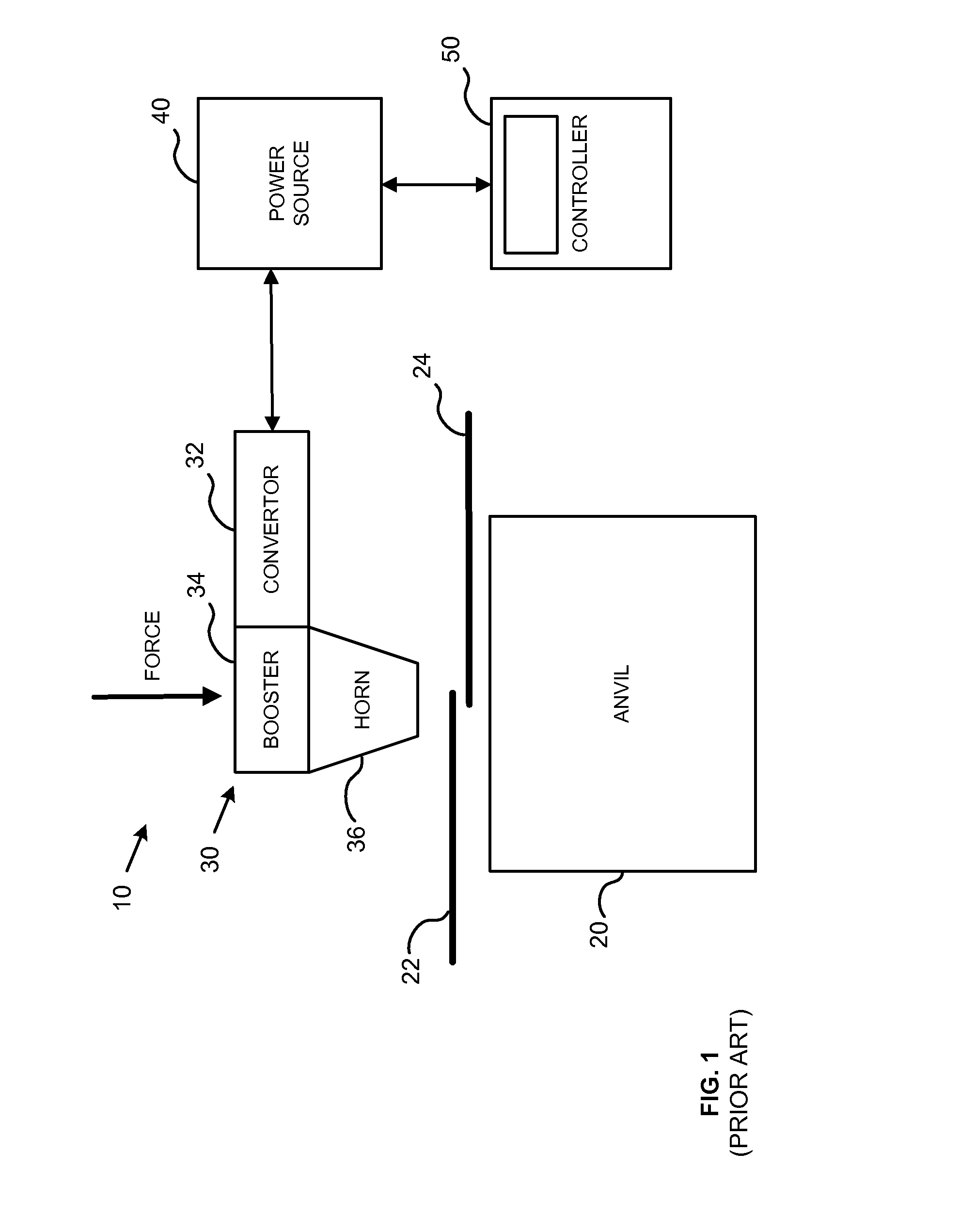
FIELD OF THE INVENTION[0001]The present invention relates to ultrasonic welding systems and methods of using the same. More specifically, the present invention relates to a method and system for testing the integrity of a stack of an ultrasonic welding system.BACKGROUND OF THE INVENTION[0002]Ultrasonic welding uses high frequency vibrations to weld two or more work pieces. This process has applications in the electronic, automotive, aerospace, appliance, and medical industries, for example, and is commonly used for metals and plastics.[0003]The process of ultrasonic welding and the equipment and systems to perform the same are generally known. In reference to FIG. 1, a generic ultrasonic welding system 10 is shown. The system 10 shown in FIG. 1 is configured to weld two wires 22, 24 using ultrasonic vibrations. The system 10 includes an anvil 20. An end of a first wire 22 and an end of a second wire 24 are positioned in an overlapping manner on a surface of the anvil 20. The system ...

Claims


Application Information

Patent Timeline
IPC IPC(8): G01N29/34B29C65/08B29C65/82G01N29/12
CPCG01N29/348G01N29/12G01N2291/267B29C65/8292B29C65/08B23K20/10B06B1/0246B06B3/00B06B2201/40B06B2201/72B23K31/125B23K2101/32B23K2101/38B29C66/1122B29C66/43B29C66/8322B29C66/96G01N29/4427
Inventor SIMON, WILLIAM P.MASSA, JOHNMARKUS, JAMES A.
Owner SONICS & MATERIALS
Learn More