
Portable cutting tool

Active Publication Date: 2015-11-26
POSITEC POWER TOOLS (SUZHOU) CO LTD
View PDF55 Cites 7 Cited by
  • Summary
  • Abstract
  • Description
  • Claims
  • Application Information

AI Technical Summary

Benefits of technology

The present invention is a portable cutting tool that has a stable state and is easy to operate. It has a compact structure with a perpendicular blade shaft and a rotatable lower guard that increases the usable part of the blade and enhances the overall cutting capacity of the tool. The tool has a gripping portion that forms a fulcrum, which restricts the parts on its sides and makes the tool stable and easy to use. The blade shaft is perpendicular to the output shaft of the motor, and its diameter is reduced by rotating the lower guard, increasing the usable part of the blade.

Problems solved by technology

Disadvantages of such conventional electric circular saw are that it is large and cumbersome, and an operator cannot use it conveniently.

Method used


Image

  • Portable cutting tool
  • Portable cutting tool
  • Portable cutting tool

Examples


Embodiment Construction

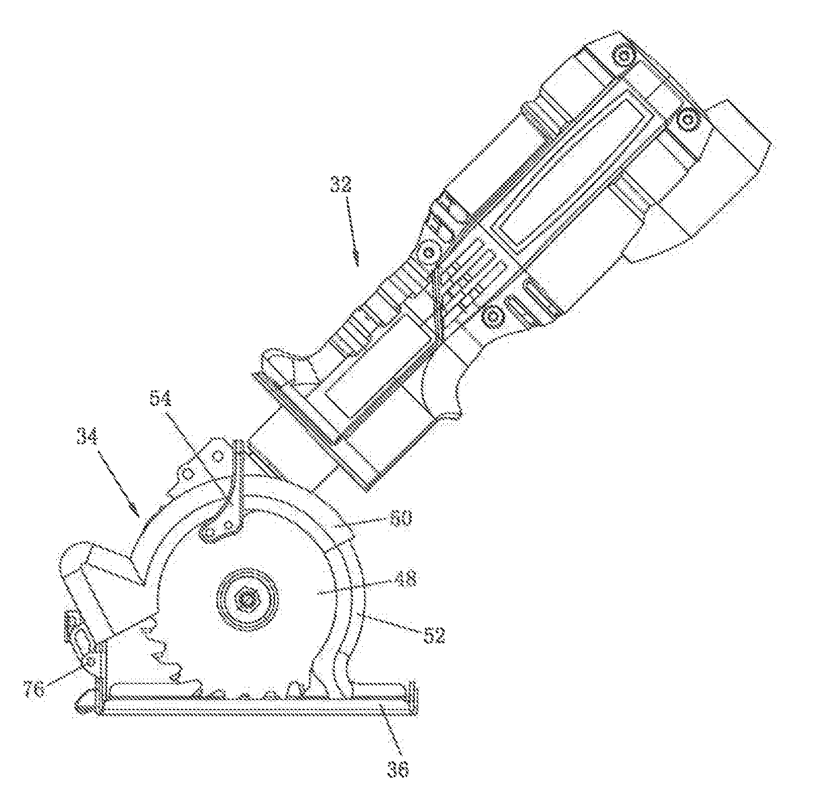
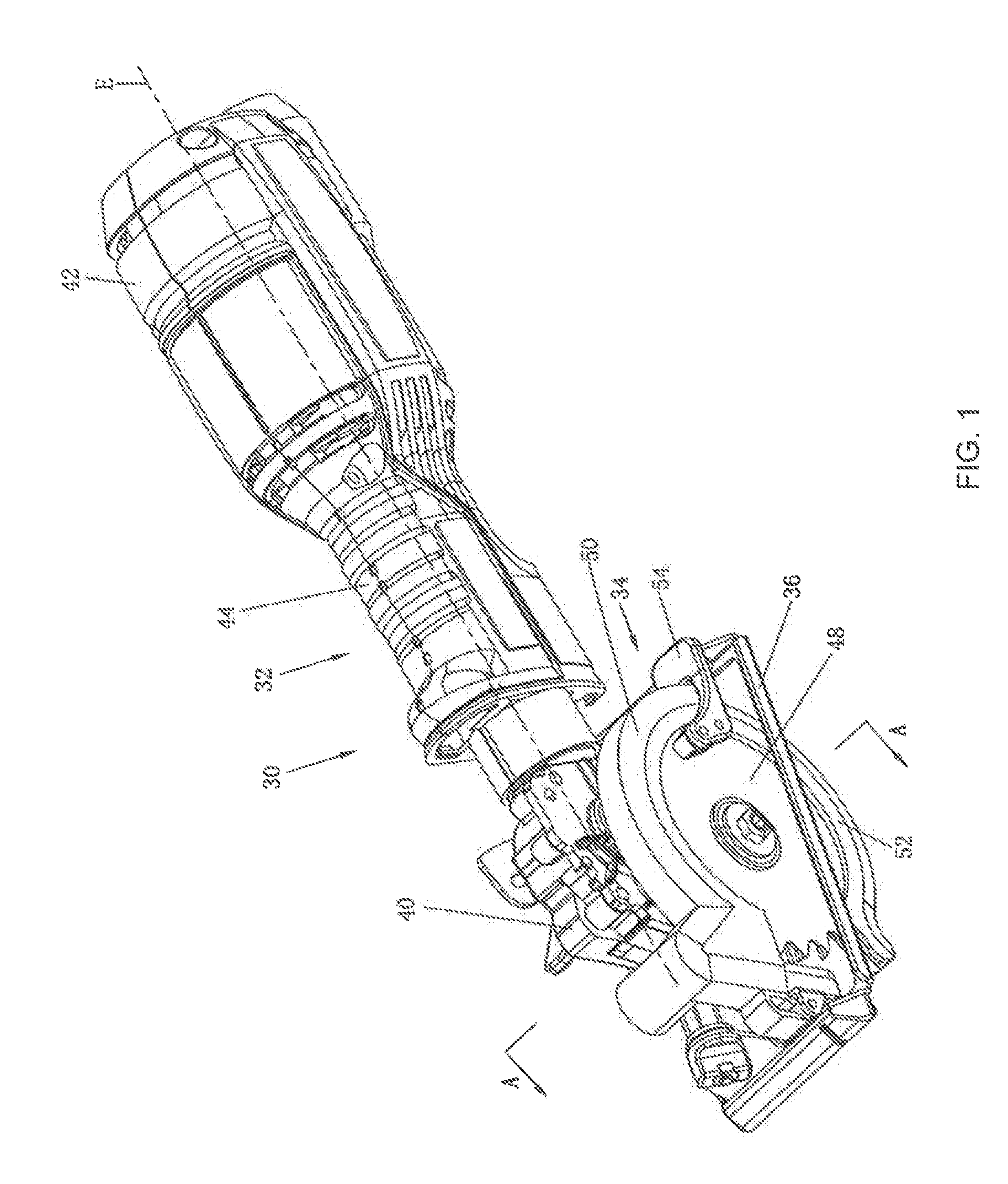
[0039]Referring to FIG. 1, an embodiment of the present invention provides a portable cutting tool 30. The portable cutting tool 30 includes a housing 32, a motor (not shown in the figure) received in the housing 32, a transmission assembly (not shown in the figure) located in the housing 32 and used for transmit power, a cutting unit 34 connected to the housing 32, a base 36 connected to the cutting unit 34, and a switch assembly (not shown in the figure) located on the housing 32 and used for controlling on / off of the motor. In the description of the present invention, unless otherwise specified, the direction related terminologies such as front, rear, left, right, upper and lower are all directions relative to normal use of the portable cutting tool, for example, it is defined that a forward direction of the portable cutting tool is front, and a direction opposite to the forward direction of the portable cutting tool is rear.

[0040]A power supply of the portable cutting tool 30 is...


PUM

PropertyMeasurementUnit
Angleaaaaaaaaaa
Angleaaaaaaaaaa
Depthaaaaaaaaaa

Abstract

The present invention provides a portable cutting tool, including: a blade; a motor used for driving the blade to rotate, where the motor has a motor output shaft; a guard assembly that includes an upper guard and a lower guard which is used for receiving the motor; a base connected to the upper guard, where the base further includes a base bottom portion used for abutting against a workpiece; and a housing that includes a front portion connected to the upper guard, a rear portion extending longitudinally, and a gripping portion disposed between the front portion and the rear portion, where the blade shaft is perpendicular to the motor output shaft. In this manner, after an operator grips the gripping portion, the portable cutting tool is in a relatively stable state, and a cutting operation can be performed easily, making the operation more comfortable.

Description

BACKGROUND[0001]1. Technical Field[0002]The present invention relates to a power tool, in particular in a portable cutting tool.[0003]2. Related Art[0004]A conventional portable cutting tool, such as a portable electric circular saw, usually includes a blade used for cutting workpieces; a motor for driving the blade, where an output shaft of the motor is usually perpendicular to the blade; and a main handle, used to be gripped by an operator during operation, where the main handle is disposed perpendicular to the motor. Such electric circular saw includes a base, an upper guard, and a lower guard. The upper guard is located on an upper part of the base for receiving the blade at any time, and the lower guard is located below the base. During working, the lower guard is rotatable to expose a lower part of the blade. Disadvantages of such conventional electric circular saw are that it is large and cumbersome, and an operator cannot use it conveniently.SUMMARY[0005]One technical proble...

Claims


Application Information

Patent Timeline
IPC IPC(8): B27B9/02B25F5/02
CPCB25F5/02B27B9/02B23D45/16B23Q11/06
Inventor BROWN, WARRENSZOMMER, HARRYGERHARDT, GRAHAM
Owner POSITEC POWER TOOLS (SUZHOU) CO LTD
Features
  • Generate Ideas
  • Intellectual Property
  • Life Sciences
  • Materials
  • Tech Scout
  • Unparalleled Data Quality
  • Higher Quality Content
  • 60% Fewer Hallucinations
Learn More