In-feed system and method for supplying can bodies to a decorator

a technology of infeed system and decorator, which is applied in the direction of mechanical conveyors, printing presses, printing, etc., can solve the problem of compromising the loading time of the mandrel

Active Publication Date: 2015-11-26
CROWN PACKAGING TECH
View PDF5 Cites 25 Cited by
  • Summary
  • Abstract
  • Description
  • Claims
  • Application Information

AI Technical Summary

Benefits of technology

[0015]An object of the infeed apparatus is to be able to handle undecorated cans at high line speeds, the aim being to handle 1000 cans per minute, or even beyond that, on each conveyor lane, with a fraction of the hardware which is about the mandrel drum of U.S. Pat. No. 3,613,571. Preferably the transfer turret has a circular pitch which is identical to that of the mandrel wheel whereby the can stability is improved for loading. Staging the can pitch change between conveyor and mandrel wheel improves the stack ‘behaviour’ by lowering the magnitude of stack shunting.
[0017]This embodiment reduces the speed of transfer from each infeed conveyor stack but requires a large pitch change between the infeed conveyor stack and the mandrel wheel circular pitch for a single infeed turret which could be mitigated by the addition of further turrets to accompany each separator turret. Multiple independent conveyor lanes and accompanying infeed turrets feeding directly into the mandrel wheel assembly compromises the mandrel loading time.
[0019]This final embodiment has the advantages of (i) reducing the speed of the infeed conveyor stack, thus leading to higher machine production speed; (ii) exchanging onto the mandrel wheel assembly (“spindle disc”) without can pitch change between combiner turret and can carrier pocket, thereby improving can stability for mandrel loading; and (iii) not compromising (i.e. optimising) mandrel loading time.

Problems solved by technology

Multiple independent conveyor lanes and accompanying infeed turrets feeding directly into the mandrel wheel assembly compromises the mandrel loading time.

Method used


Image

  • In-feed system and method for supplying can bodies to a decorator
  • In-feed system and method for supplying can bodies to a decorator
  • In-feed system and method for supplying can bodies to a decorator

Examples


Embodiment Construction

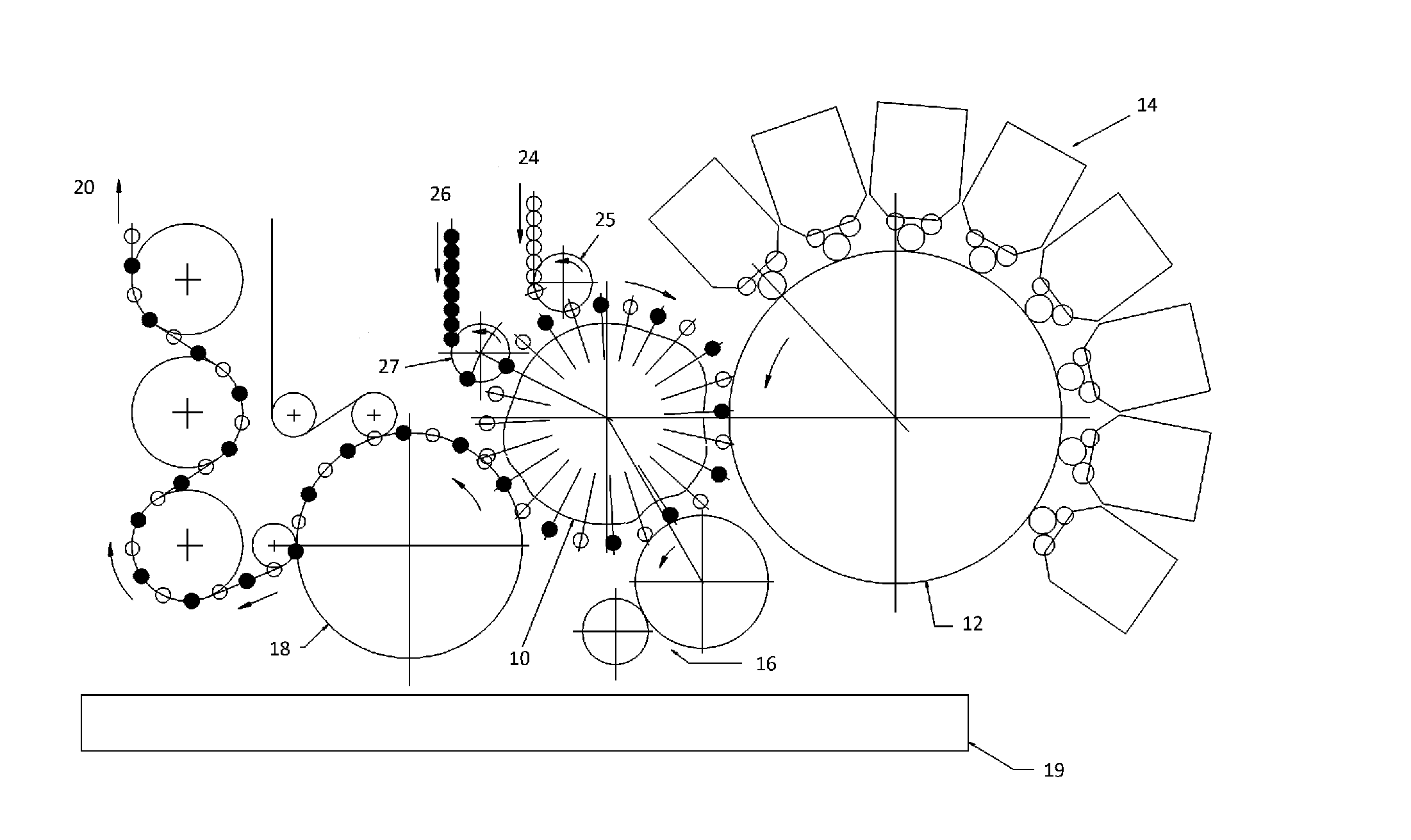
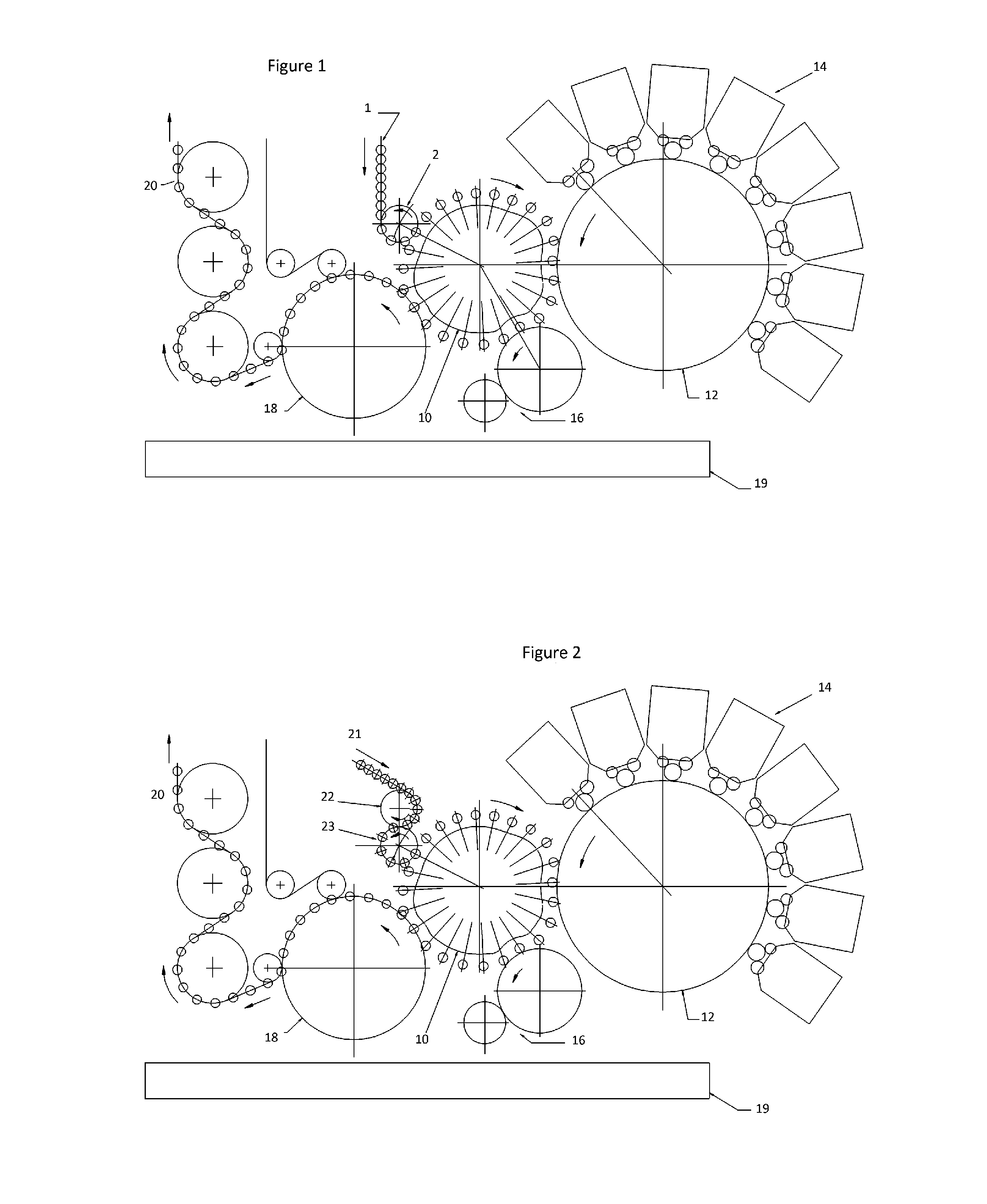
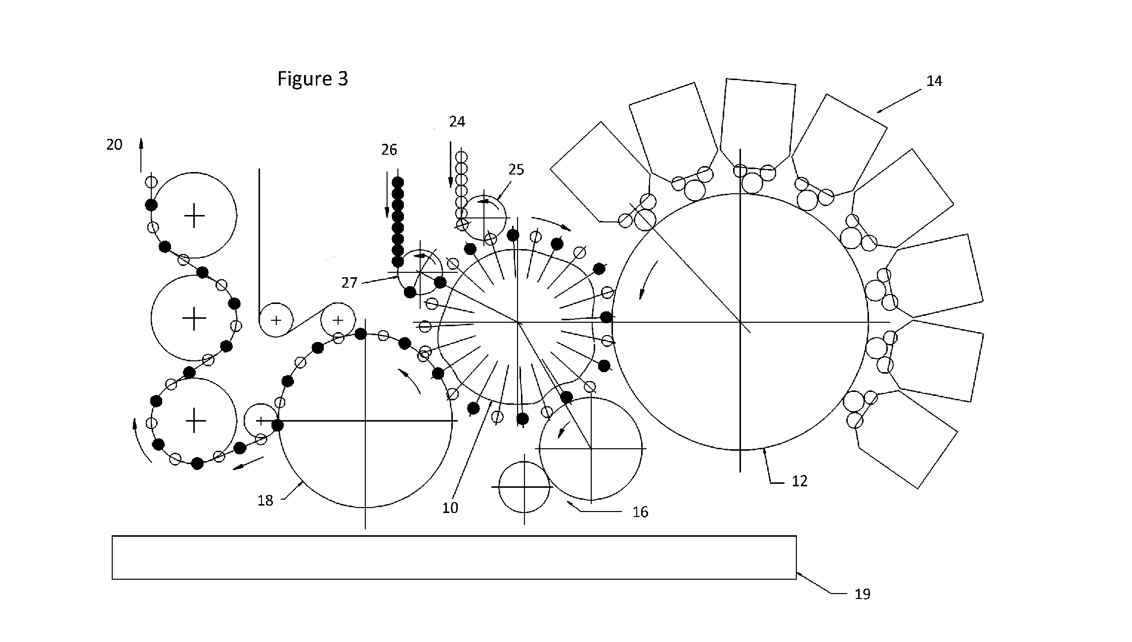
[0026]FIG. 1 shows a known infeed system and associated decorator. The infeed system comprises a conveyor stack 1 in which can bodies are stacked and thereby in contact with each other and having a linear pitch. An infeed separator turret 2 separates and re-pitches the can bodies from the stack 1. It is apparent from FIG. 1 that there is a pitch change inherent in the change from the linearly pitched stack to the separator turret 2 and, additionally, in the transfer from the infeed separator turret 2 to the mandrel wheel assembly 10 of the can body decorator.

[0027]Although not featured in the conventional system of FIG. 1, some machine manufacturers omit the infeed separator turret and guide the can onto a profiled “can carrier pocket” which is mounted in front of the mandrel. The mandrel is part of the mandrel wheel assembly (cf. 10) and the can carrier pocket has the function of changing can conveyor pitch to that of the mandrel wheel circular pitch.

[0028]The remainder of the feat...


PUM


Abstract

An infeed system for a can body decorator in which undecorated can bodies are transported from an upstream supply in a conveyor (21). In the conveyor (21), the can bodies have a linear pitch as they are touching each other. One or more infeed turrets (22, 23; 25, 27; 28, 9, 3) separate each can body and change the pitch to the circular pitch of a separator turret and, ultimately to that of the mandrel wheel (10) in the decorator assembly.

Description

TECHNICAL FIELD[0001]This invention relates to an infeed system for supplying undecorated can bodies to a can body decorator. In particular, but not exclusively, it relates to a combination of one or more conveyors, infeed separator turrets and transfer turrets which together change the can pitch to that of a mandrel wheel assembly (sometimes referred to as a “spindle disc”) in the can body decorator. For the avoidance of doubt, the term “decorator” is intended to include the application of any kind of decoration, print, coloured inks or varnish onto a can body which is typically formed from tin free steel, aluminium or other metal. The term “can” is used herein to mean the can body prior to filling and closing to form a finished can.BACKGROUND ART[0002]U.S. Pat. No. 4,138,041 (COORS CONTAINER COMPANY) describes a gravity infeed through an inclined chute to stationary pockets on a rotatable pocket mandrel wheel. There, the cans are drawn from the pockets and seated by vacuum on mand...

Claims


Application Information

Patent Timeline
Patent Type & Authority Applications(United States)
IPC IPC(8): B65G47/84B41F17/22B41F17/00B65G37/00B65G29/00
CPCB65G47/846B65G37/00B41F17/22B41F17/002B65G29/00B65G2201/0235
Inventor COATES, MICHAEL JONATHANEGERTON, DANIEL
Owner CROWN PACKAGING TECH
Why Eureka
Try Eureka