
Combustion apparatus having air intake preheater

a combustion apparatus and air intake technology, applied in lighting and heating apparatus, combustion types, instruments, etc., can solve the problems of increasing the emission amount of carbon dioxide (cosub>2/sub>), reducing the combustion efficiency of combustion apparatus, etc., to reduce the combustion load of the burner, improve combustion efficiency, and reduce the flame temperature and fuel consumption

Active Publication Date: 2015-11-26
KYUNGDONG NAVIEN
View PDF7 Cites 14 Cited by
  • Summary
  • Abstract
  • Description
  • Claims
  • Application Information

AI Technical Summary

Benefits of technology

The present invention provides a combustion apparatus with an air intake preheater that can reduce the load of the burner and improve combustion efficiency. The air intake preheater is designed with multiple unit plates that alternate between exhaust gas channels and air intake channels, allowing for the recirculation of exhaust gas to the air intake side using the pressure difference caused by the venturi structure. This recirculation helps to lower the flame temperature and reduces fuel consumption, resulting in reduced emissions of nitrogen oxide and carbon dioxide, making it an eco-friendly combustion apparatus.

Problems solved by technology

Thus, the combustion apparatus is reduced in combustion efficiency, and also as fuel consumption increases, an emission amount of carbon dioxide (CO2) increases.

Method used


Image

  • Combustion apparatus having air intake preheater
  • Combustion apparatus having air intake preheater
  • Combustion apparatus having air intake preheater

Examples


Embodiment Construction

[0032]Hereinafter, components and effects of a combustion apparatus according to a preferred embodiment of the present invention will be described in detail with reference to the accompanying drawings.

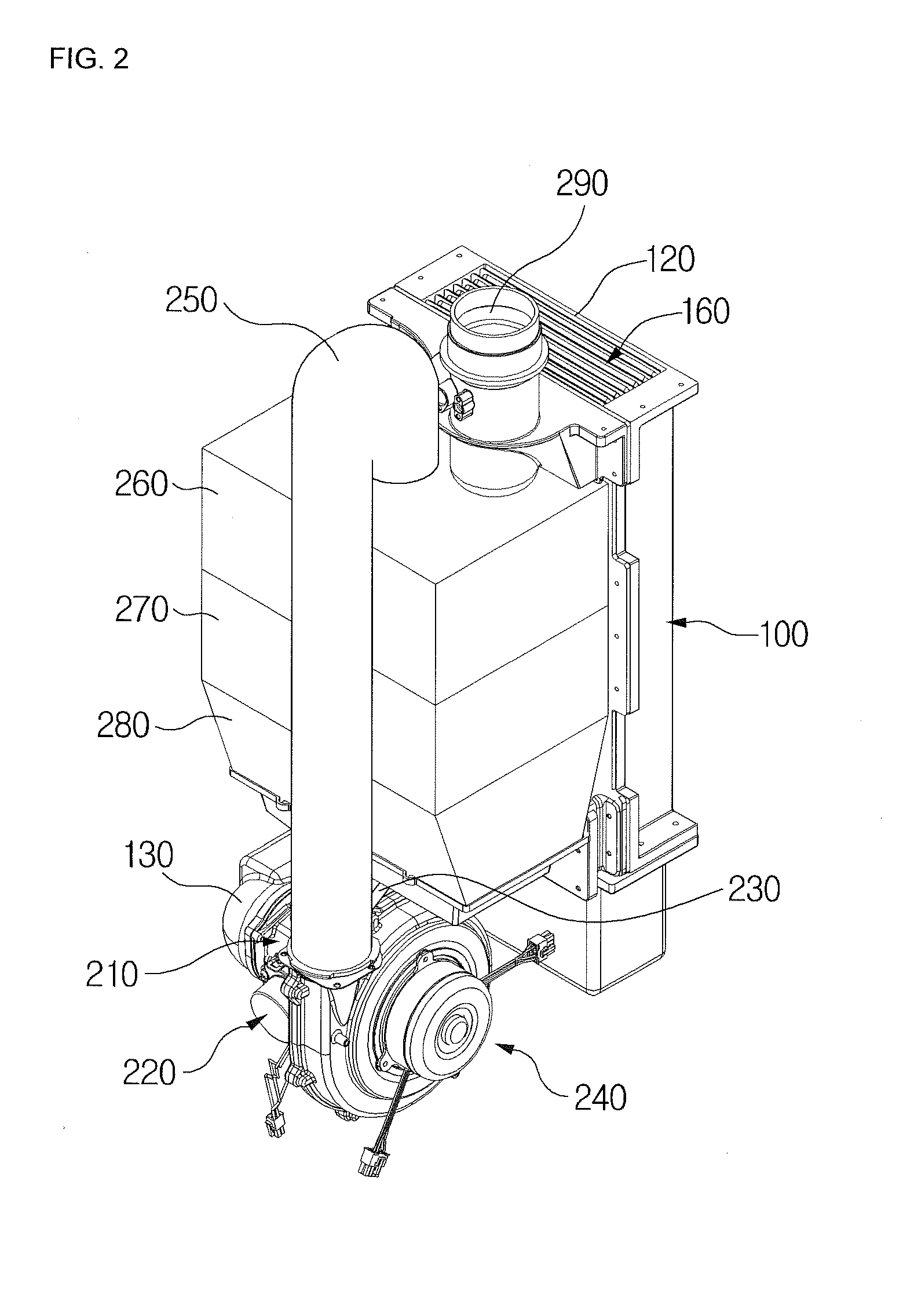
[0033]Referring to FIG. 2, the combustion apparatus according to the present invention includes a premixing chamber 210, a mixed-gas adjusting part 220 for adjusting an air-fuel ratio of the mixed-gas that is premixed in the premixing chamber 210 in proportional to a combustion load, a blower 240 supplying the mixed-gas of the premixing chamber 210 to a burner, a mixed-gas supply tube 250 through which the mixed-gas transferred from the blower 240 is supplied to the burner, a combustion chamber 260 in which the mixed-gas is burnt by ignition of the burner, a heat exchanger 270 in which heating water is heat-exchanged with combustion heat generated from the combustion chamber 260, an exhaust gas discharge part 280 from which an exhaust gas passing through the heat exchanger 270 is disch...


PUM


Abstract

The present invention relates to a combustion apparatus capable of reducing the combustion load of a burner and improving the combustion efficiency thereof. The combustion apparatus includes: a premixing chamber for premixing external air, introduced through an air supply inlet, with a combustion gas; a blower for supplying a mixed air premixed in the premixing chamber toward a burner; a combustion chamber for burning the mixed air by ignition of the burner; a heat exchanger for heat exchange with room heating water by using the combustion heat of the combustion chamber; an exhaust gas discharging part for discharging an exhaust gas having passed through the heat exchanger; and a duct through which the exhaust gas having passed through the exhaust gas discharging part is discharged outside, wherein the combustion apparatus includes an air intake preheater for heat exchange between the exhaust gas discharged to the duct through the exhaust gas discharging part and the air supplied to the premixing chamber through the air supply inlet, the air intake preheater including a channel-forming member in which a plurality of unit plates are stacked with a predetermined interval therebetween to form an exhaust gas channel and an air intake channel therein that are separated from each other, are adjacent to each other, and are alternately arranged.

Description

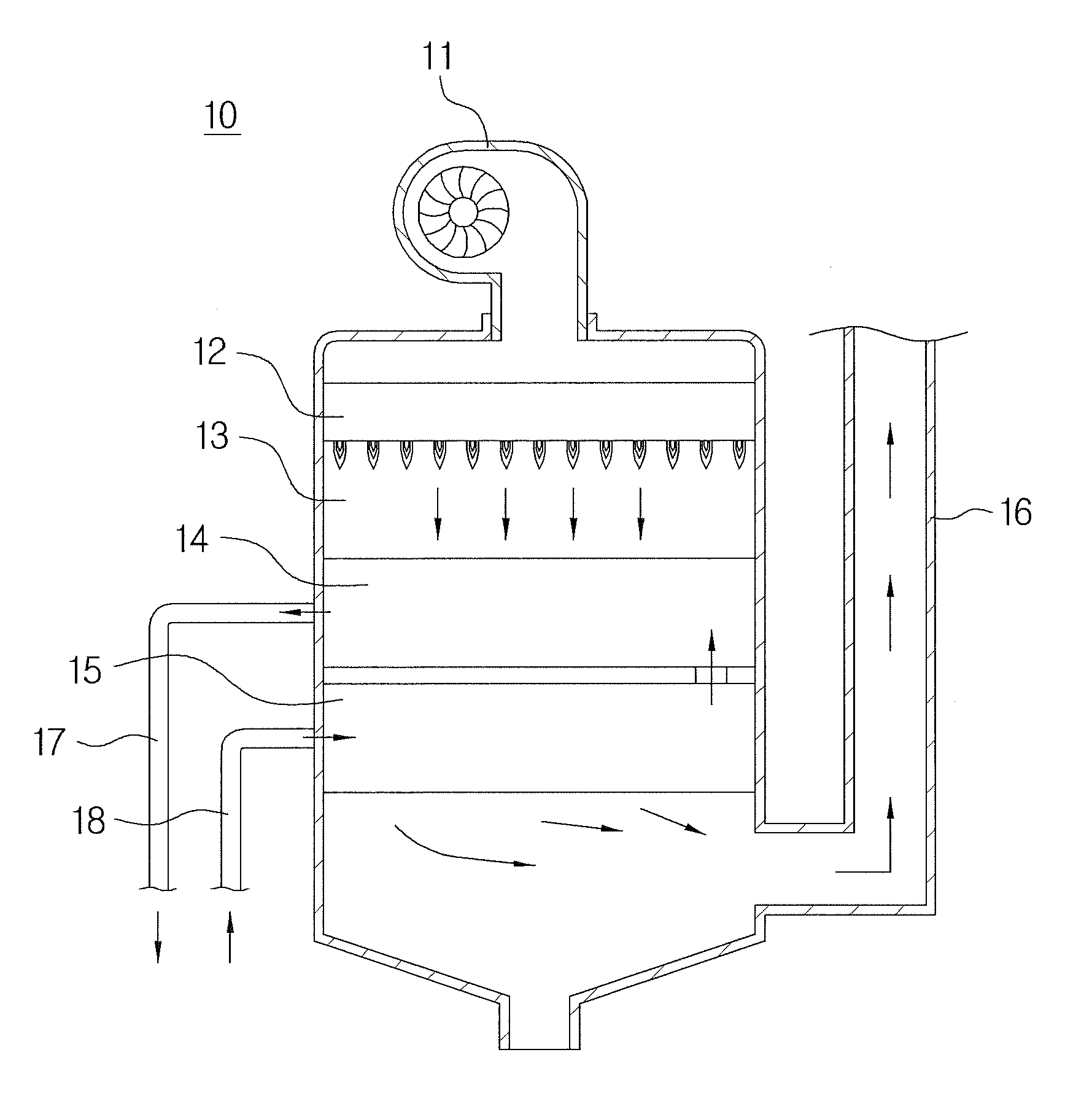
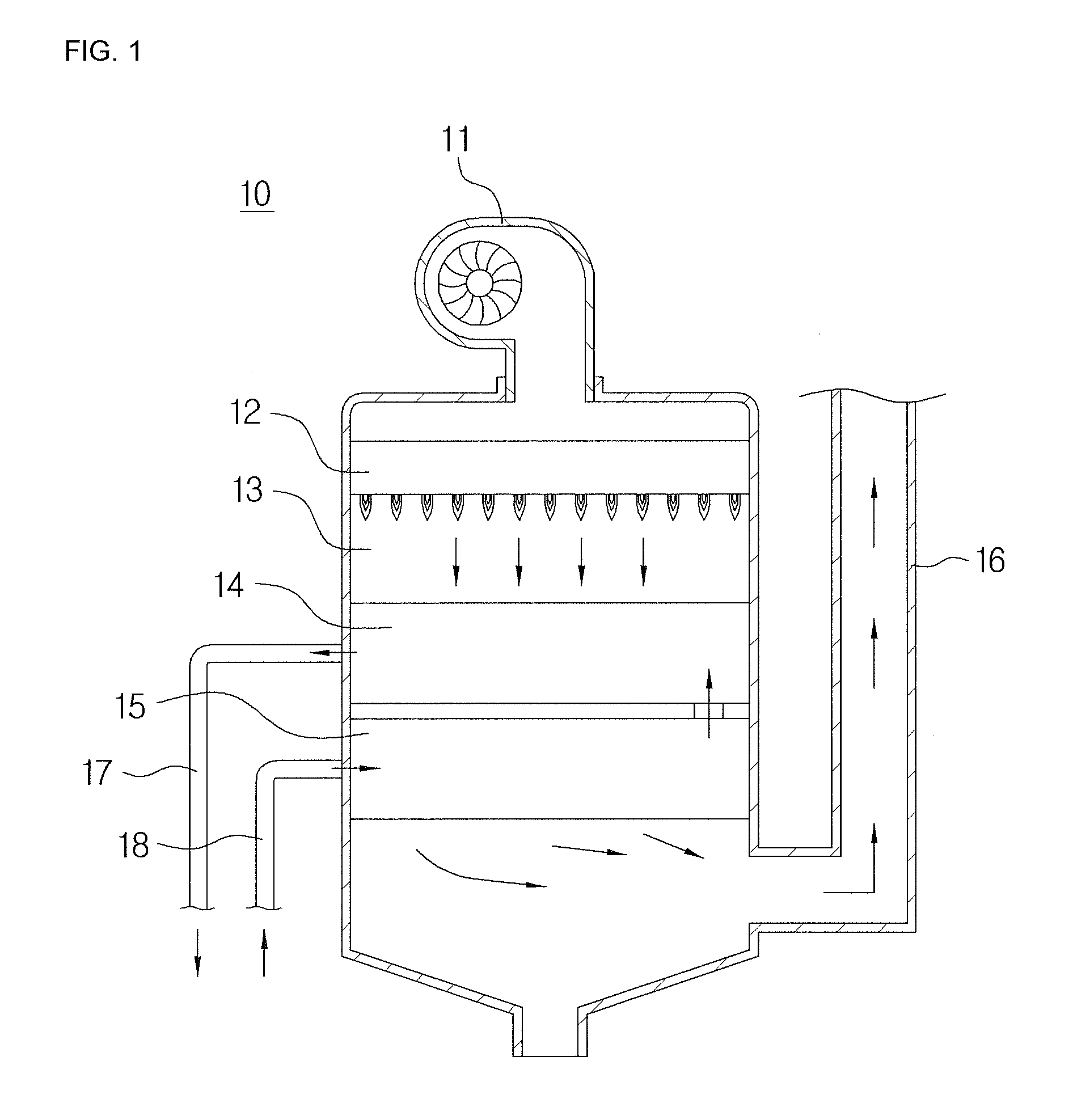
TECHNICAL FIELD[0001]The present invention relates to a combustion apparatus having an air intake preheater, and more particularly, to a combustion apparatus having an air intake preheater in which air supplied to the air intake preheater is preheated by using waste heat of an exhaust gas discharged after heat-exchanged with heating water, and a portion of the exhaust gas recirculates to an air intake side to improve heat efficiency of a combustion apparatus and reduce a flame temperature, thereby reducing emission amounts of nitrogen oxide and carbon dioxide.BACKGROUND ART[0002]Combustion apparatuses such as boilers or water heaters are devices in which heating water in a sealing container is heated by a heat source to heat a desired area or supply hot water. The combustion apparatus is constituted by a burner burning mixed-gas in which a gas is mixed with air and a heat exchanger for transmitting combustion heat of a combustion gas to the heating water or direct water.[0003]FIG. 1...

Claims


Application Information

Patent Timeline
Patent Type & Authority Applications(United States)
IPC IPC(8): F24H9/00F23L15/00F24H1/14F23C7/00
CPCF24H9/0084F23C7/002F23L15/00F23L2900/00F23C2202/10F23L2900/15021F24H1/145F23D14/66F28D9/0043F28D21/0003F28D21/0008F23L15/04Y02E20/34Y02B30/00G01F17/00G01D13/12
Inventor KIM, YOUNG MO
Owner KYUNGDONG NAVIEN
Learn More