Method for the location determination of the involutes in gears

a technology of involutes and gears, applied in the direction of electrical programme control, program control, instruments, etc., can solve the problems of insufficient measurement between two measurement points, and inability to use measured results with restrictions

Active Publication Date: 2015-11-26
LIEBHERR VERZAHNTECHNIK GMBH
View PDF12 Cites 20 Cited by
  • Summary
  • Abstract
  • Description
  • Claims
  • Application Information

AI Technical Summary

Benefits of technology

[0048]The advantages and properties of the gear-cutting machine in accordance with the present disclosure obviously correspond to those of the corresponding methods in accordance with the present disclosure so that a repeat description will be dispensed with at this point.

Problems solved by technology

The determination of the location of the involutes is usually very uncomplicated with symmetrical spur gears.
If the contact is established at such a surface between the workpiece and the tool, the measured result can only be used with restrictions.
If in contrast the tooth flanks differ considerably between the right tooth flank and the left tooth flank and / or if the tooth flanks are also designed conically over the tooth width for this purpose, an averaging between two measurement points is no longer sufficient to describe the location of the involutes or an incorrect position may result from this.
This is above all not very simple with very conical and / or asymmetrical gears.
This could result in transmission damage in the assembled transmission under working conditions and thus in a premature end of the transmission service life.
As soon as a workpiece or tool having an asymmetrical or conical flank shape is used, such processes deliver erroneous results.
In this case, a roller-coupled rotation of the transmission is only possible about a small angle since there is otherwise a risk of collisions with other teeth.
There is the risk that the result of the location determination of the involutes is falsified when one or both of the gears of the workpiece or tool are modified.
They occur in tools, for example, due to wear defects or production defects and / or are deliberately placed into the tool to generate modifications directly on the workpiece.
This process was previously only possible in an automated manner for symmetrically cylindrical gears.
The carrying out of the method can in particular be problematic in the location determination or in the centering of tools having narrow gears and unfavorable contact conditions.
A contact with the edge of the gear takes place and a precise centering is no longer possible.
Such insertion sensors can generally not determine the absolute location of the workpiece, but rather only the location relative to a reference location, which makes such a teaching necessary.

Method used


Image

  • Method for the location determination of the involutes in gears
  • Method for the location determination of the involutes in gears
  • Method for the location determination of the involutes in gears

Examples


Embodiment Construction

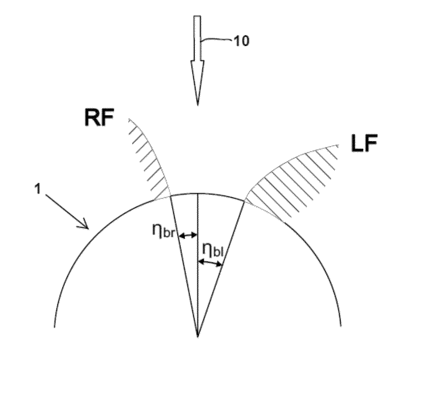
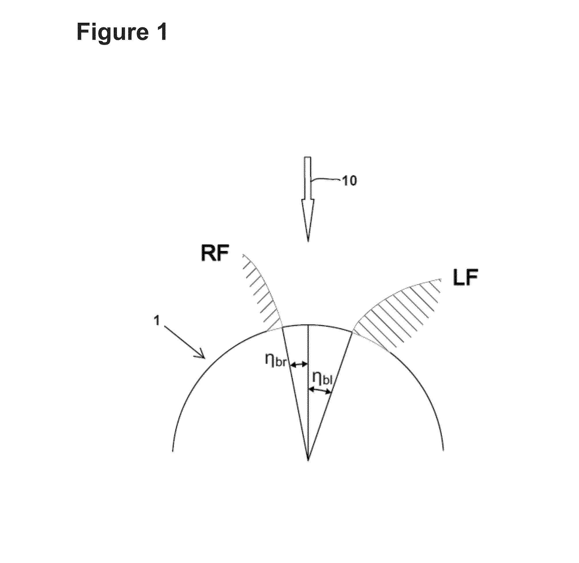
[0060]The method in accordance with the present disclosure for the measurement of a gear wheel will be described in detail in the following. The geometrical properties of asymmetrical and / or conical gears are in particular considered in the method in accordance with the present disclosure. The taking into account of these properties in conjunction with a defined calculation provision allows the calculation of the location of the involutes on the left and right tooth flanks of a gear wheel to be measured. The method can moreover be used for a simple allowance determination of a workpiece using a tool, a location-dependent machining of gears and for centering gears and tools.

[0061]In the method in accordance with the present disclosure, the tool and the workpiece form a helical rolling type gear transmission of two outer gears or of one outer gear and one inner gear. The workpiece and / or the tool can have both an asymmetrical cylindrical gear and a conical gear (beveloid gear). The wo...


PUM


Abstract

A method for the location determination of the involutes of a pre-gear cut workpiece within a gear-cutting machine using a gear-cut tool comprising the method steps: generating first and second relative movements between the workpiece and the tool; detecting respective, resulting first and second contact between a first tooth flank of the tool and a first tooth flank of the workpiece; and detecting a respective first and second set of coordinates for representing the relative movement of the workpiece and the tool; and determining the angles of rotation, the feeds, the axial distance and the crossed-axes angle of the tool and the workpiece based on the first and second set of coordinates and subsequent calculation of the location of the involutes on the basis of the angles of rotation, the feeds, the axial distance and the crossed-axes angle.

Description

CROSS REFERENCE TO RELATED APPLICATIONS[0001]This application claims priority to German Patent Application No. 10 2014 007 646.6, entitled “Method for the Location Determination of the Involutes in Gears”, filed May 23, 2014, and also claims priority to European Patent Application No. 15 164 833.4 filed Apr. 23, 2015, entitled “Method for the Location Determination of the Involutes in Gears”, which are hereby incorporated by reference in their entirety for all purposes.TECHNICAL FIELD[0002]The present disclosure relates to a method for the location determination of the involutes of a workpiece, preferably of a gear wheel having a conical and / or asymmetrical involute gear and to a method for the location-orientated production of a workpiece.BACKGROUND AND SUMMARY[0003]The determination of the location of the involutes is usually very uncomplicated with symmetrical spur gears. The position of the right flank and of the left flank is determined at a point and the path between these poi...

Claims


Application Information

Patent Timeline
Patent Type & Authority Applications(United States)
IPC IPC(8): G01B5/24G05B19/414G01B5/008B23F23/12B23Q17/20B23Q17/22
CPCG01B5/24B23Q17/20B23Q17/2241G05B2219/36198B23F23/12G05B19/4145G01B5/008G05B19/402B23F23/006B23F23/1218B23F5/00
Inventor WUERFEL, ROBERT
Owner LIEBHERR VERZAHNTECHNIK GMBH
Why Eureka
Try Eureka