Integrated dual axis fluxgate sensor using double deposition of magnetic material

a dual-axis, magnetic material technology, applied in the field of fluxgates, can solve problems such as difficulty in measuring the in-plane magnetic field

Active Publication Date: 2015-11-26
TEXAS INSTR INC
View PDF1 Cites 34 Cited by
  • Summary
  • Abstract
  • Description
  • Claims
  • Application Information

AI Technical Summary

Benefits of technology

[0012]The following presents a simplified summary in order to provide a basic understanding of one or more aspects of the invention. This summary is not an extensive overview of the invention, and is neither intended to identify key or critical elements of the invention, nor to delineate the scope thereof. Rather, the primary purpose of the summary is to present some concepts of the invention in a simplified form as a prelude to a more detailed description that is presented later.

Problems solved by technology

This is fine for measuring the magnetic field in one specific direction, but this makes it difficult to measure the in-plane magnetic field, which is essential for e-compass applications.

Method used


Image

  • Integrated dual axis fluxgate sensor using double deposition of magnetic material
  • Integrated dual axis fluxgate sensor using double deposition of magnetic material
  • Integrated dual axis fluxgate sensor using double deposition of magnetic material

Examples


Embodiment Construction

[0026]The present invention is described with reference to the attached figures. The figures are not drawn to scale and they are provided merely to illustrate the invention. Several aspects of the invention are described below with reference to example applications for illustration. It should be understood that numerous specific details, relationships, and methods are set forth to provide an understanding of the invention. One skilled in the relevant art, however, will readily recognize that the invention can be practiced without one or more of the specific details or with other methods. In other instances, well-known structures or operations are not shown in detail to avoid obscuring the invention. The present invention is not limited by the illustrated ordering of acts or events, as some acts may occur in different orders and / or concurrently with other acts or events. Furthermore, not all illustrated acts or events are required to implement a methodology in accordance with the pre...


PUM


Abstract

A method of fabricating fluxgate devices to measure the magnetic field in two orthogonal, in plane directions, by using a composite-anisotropic magnetic core structure.

Description

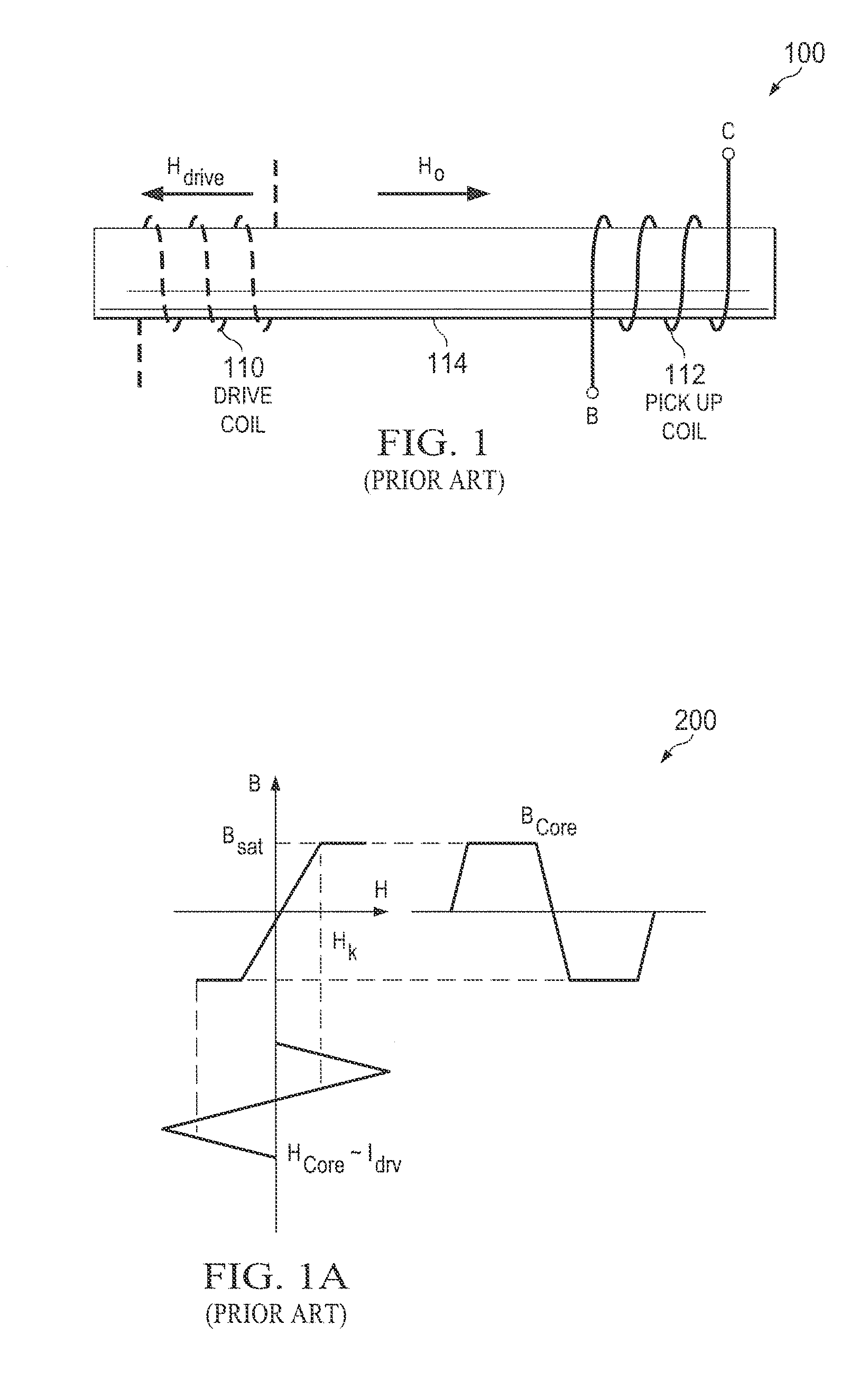
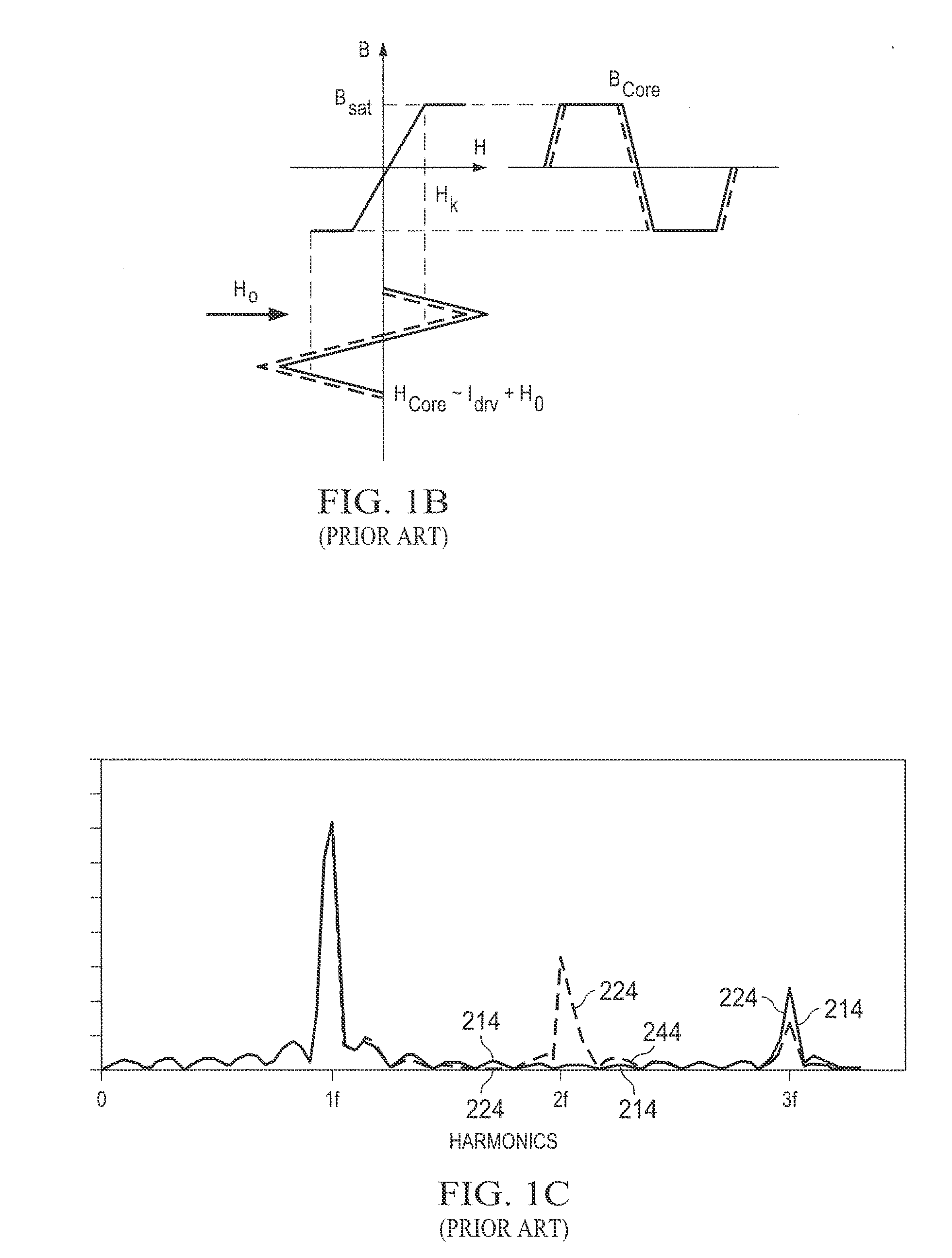
FIELD OF THE INVENTION[0001]The present invention relates to fluxgates and, more particularly, to a semiconductor fluxgate sensor.BACKGROUND OF THE INVENTION[0002]A magnetic sensor is a device that measures the strength of an external magnetic field. There are a number of different approaches to measuring magnetic fields, and various different types of magnet sensors have been developed based on these different approaches. One type of magnetic sensor based on flux variations in a magnetic core is a fluxgate sensor.[0003]FIG. 1 shows a block diagram that illustrates an example of a prior art fluxgate sensor 100. As shown in FIG. 1, fluxgate sensor 100 includes a drive coil 110, a sense coil 112, and a magnetic core structure 114 that lies within drive coil 110 and sense coil 112.[0004]FIGS. 1A-1B show views that illustrate the operation of fluxgate magnetic sensor 100. FIG. 1A shows a graph that illustrates a BH curve 200 for magnetic core structure 114, while FIG. 1B shows a graph t...

Claims


Application Information

Patent Timeline
Patent Type & Authority Applications(United States)
IPC IPC(8): G01R33/09H01L43/12H01L29/26H01L43/00
CPCG01R33/09H01L29/26H01L43/12H01L43/00G01R33/04H10N50/00H10N50/01H10N50/80H10N50/85G01R33/0052
Inventor MOHAN, ANURAAGLEE, DOK WONFRENCH, WILLIAMMAZOTTI, ERIKA L.
Owner TEXAS INSTR INC
Why Eureka
Try Eureka