Carbon nanowall and production method thereof, oxygen reduction catalyst, oxygen reduction electrode and fuel cell
a carbon nanotube and electrode technology, applied in the field of carbon nanotubes, can solve the problems of increasing the manufacturing cost of electrodes, and achieve the effect of low cos
- Summary
- Abstract
- Description
- Claims
- Application Information
AI Technical Summary
Benefits of technology
Problems solved by technology
Method used
Image

Examples
first embodiment
[0043]An oxygen reduction catalyst according to a first embodiment is a carbon nanowall doped with nitrogen or nitrogen-doped carbon nanowall pieces. Moreover, an oxygen reduction electrode according to the first embodiment includes: a gas diffusion layer; and an oxygen reduction catalyst that is to be a catalyst layer. Further, a fuel cell according to the first embodiment comprises: an electrolyte membrane; a gas diffusion layer; an oxygen reduction catalyst that is to be the catalyst layer; and a separator.
[0044](Oxygen Reduction Catalyst)
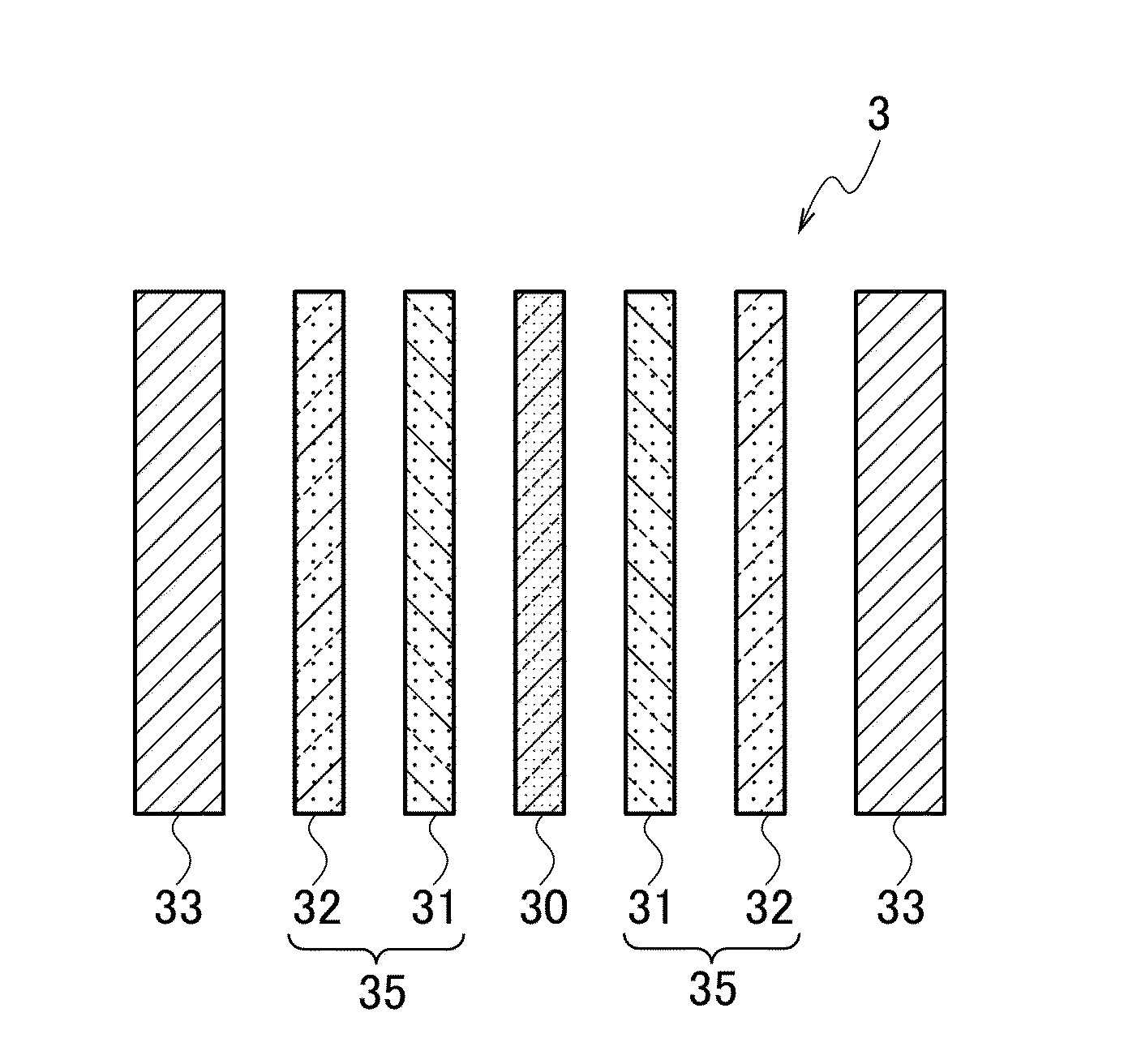
[0045]The oxygen reduction catalyst according to the first embodiment is the carbon nanowall doped with nitrogen or carbon nanowall pieces composed of one or plural domains of nanographite which are smaller than the carbon nanowall. The carbon nanowall pieces are obtained by pulverizing the carbon nanowall doped with nitrogen. The carbon nanowall doped with nitrogen is produced on a substrate, for example, a silicon substrate or the like, and it...
example 1
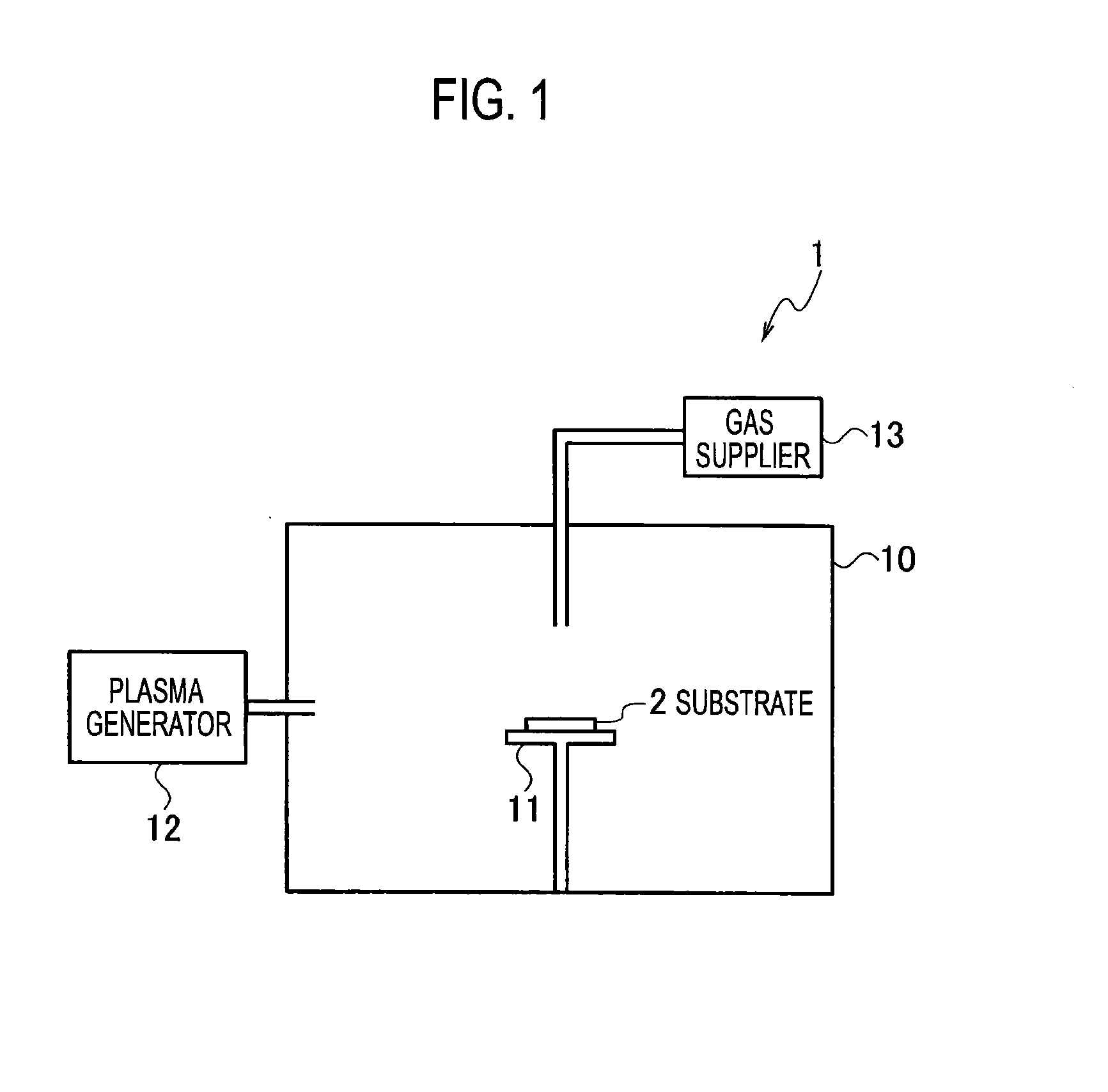
[0062]FIG. 4 illustrates a SEM image of the carbon nanowall according to Example 1. This carbon nanowall doped with nitrogen was obtained by: producing a carbon nanowall on a silicon substrate under Condition B1 by utilizing the apparatus 1 that was described above with reference to FIG. 1; and subsequently doping the carbon nanowall on the silicon substrate with nitrogen under Condition B2.
[0063]Condition B1: pressure of 0.67 Pa; heating temperature of 600° C.; a discharge current of 50 A; a flow rate of argon of 80 sccm; a flow rate of hydrogen of 10 sccm; a flow rate of methane of 10 sccm; and a growth time of 360 minutes.
[0064]Condition B2: pressure of 0.67 Pa; heating temperature of 700° C.; a discharge current of 70 A; a flow rate of argon of 80 sccm; a flow rate of hydrogen of 0 sccm; a flow rate of nitrogen of 20 sccm; and a processing time of 1 minute.
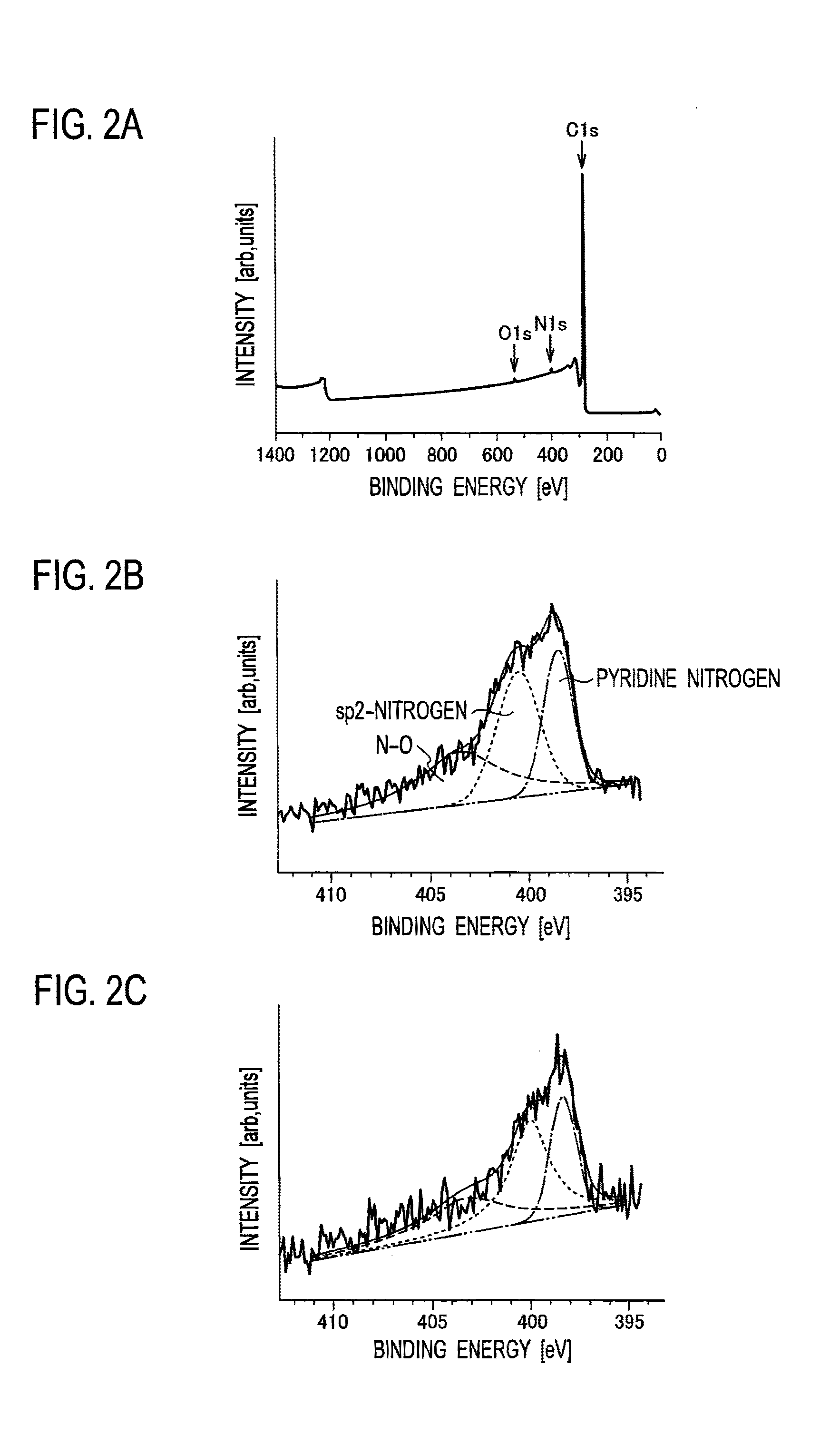
[0065]FIG. 5A illustrates a Raman scattering spectrum of the carbon nanowall doped with nitrogen of Example 1. FIG. 5B illus...
example 2
[0069]A carbon nanowall doped with nitrogen of Example 2 was obtained by: producing a carbon nanowall on a silicon substrate under Condition C1 by utilizing the apparatus 1 that was described above with reference to FIG. 1; and doping the carbon nanowall on the silicon substrate with nitrogen under Condition C2.
[0070]Condition C1: pressure of 0.67 Pa; heating temperature of 800° C.; a discharge current of 50 A; a flow rate of argon of 80 sccm; a flow rate of hydrogen of 0 sccm; a flow rate of methane of 20 sccm; and a growth time of 360 minutes.
[0071]Condition C2: pressure of 0.67 Pa; heating temperature of 800° C.; a discharge current of 50 A; a flow rate of argon of 80 sccm; a flow rate of hydrogen of 10 sccm; a flow rate of nitrogen of 10 sccm; and a processing time of 1 minute.
[0072]FIG. 6A illustrates a Raman scattering spectrum of the carbon nanowall doped with nitrogen of Example 2. FIG. 6B illustrates an XPS spectrum of the carbon nanowall of Example 2. FIG. 6C illustrates a...
PUM
| Property | Measurement | Unit |
|---|---|---|
| Temperature | aaaaa | aaaaa |
| Temperature | aaaaa | aaaaa |
| Degree of crystallinity | aaaaa | aaaaa |
Abstract
Description
Claims
Application Information