Wireless inductive power transfer

a technology of inductive power transfer and wireless, which is applied in the direction of transmission, transformers, inductances, etc., can solve the problems of reducing the impact of operational characteristics of power transfer, reducing the sensitivity of communication to level variations of power source signals, etc., to facilitate implementation, improve performance, and facilitate implementation.

Active Publication Date: 2015-11-26
KONINKLJIJKE PHILIPS NV
View PDF9 Cites 37 Cited by
  • Summary
  • Abstract
  • Description
  • Claims
  • Application Information

AI Technical Summary

Benefits of technology

[0079]In accordance with an optional feature of the invention, the frequency converter comprises a switch bridge for generating the drive signal, and the limiter may be arranged to restrict the power signal by gradually changing a relative phase of switch elements of the switch bridge. At the onset of a repeating time interval, the phase may be gradually shifted (e.g. with a transition duration of no less than 200 μs, or no less than 5% of the duration of the repeating time interval). This may provide facilitated implementation and / or improved performance.
[0080]In accordance with an optional feature of the invention the frequency converter comprises a switch bridge for generating the drive signal, and the limiter is arranged to restrict the power signal by instantaneously changing drive signals for all switch elements of the switch bridge to switch all switch elements off. This may provide facilitated implementation and / or improved performance. The switch elements may specifically be e.g. FETs or IBGTs having internal diodes, and the switch elements may be arranged such that at least some of the internal diodes may conduct current from the coil to the power source when all switch elements are switched off. This may reduce the overall power consumption as the energy stored in the resonance circuits / magnetic field may be fed back to the power source.

Problems solved by technology

It may in particular reduce the impact of operational characteristics of the power transfer on the communication operation, and vice versa.
The approach may result in reduced sensitivity of the communication to level variations of the power source signal.

Method used


Image

  • Wireless inductive power transfer
  • Wireless inductive power transfer
  • Wireless inductive power transfer

Examples


Embodiment Construction

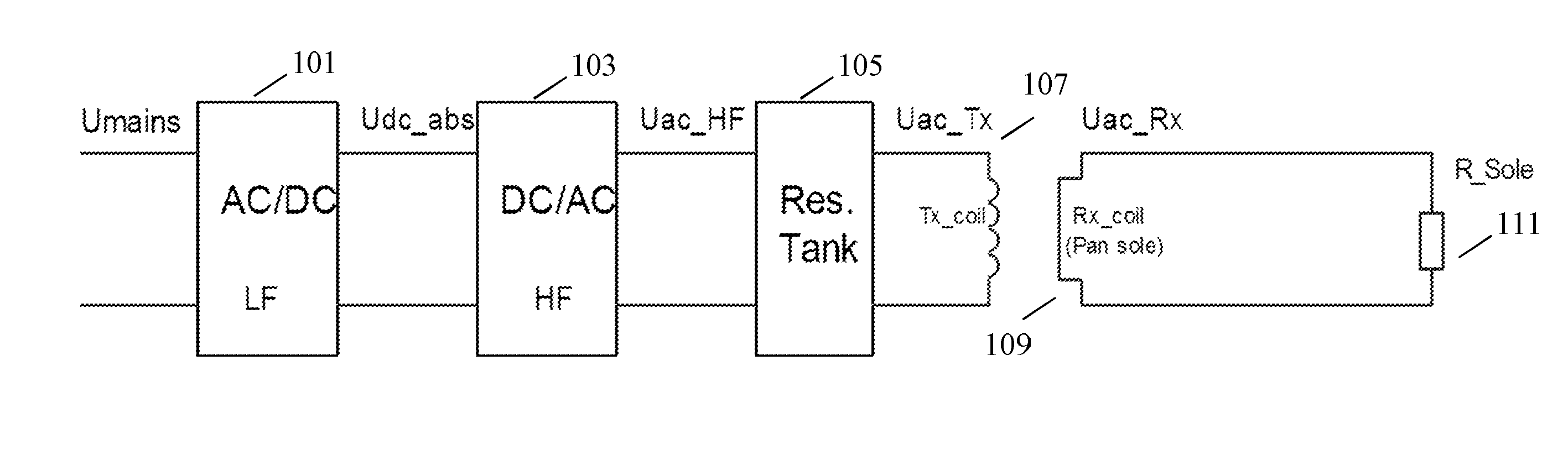
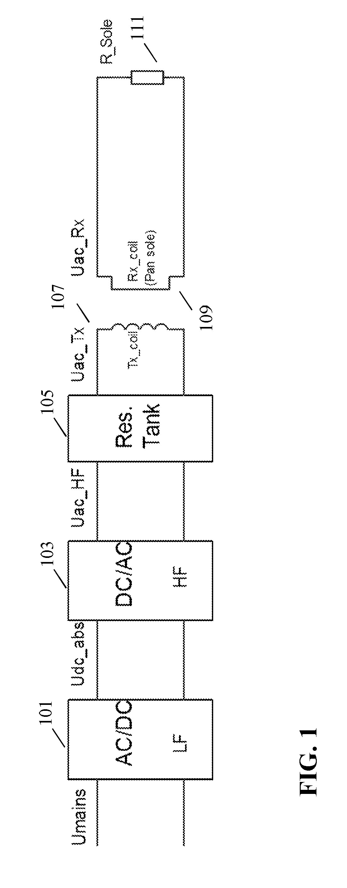
[0142]FIG. 5 illustrates an example of a power transfer system in accordance with some embodiments of the invention. The power transfer system comprises a power transmitter 501 which includes (or is coupled to) a transmitter coil / inductor 503. The system further comprises a power receiver 505 which includes (or is coupled to) a receiver coil / inductor 507.

[0143]The system provides a wireless inductive power transfer from the power transmitter 501 to the power receiver 505. Specifically, the power transmitter 501 generates a power signal which is propagated as a magnetic flux by the transmitter coil 503. The power signal may typically have a frequency between around 20 kHz to 200 kHz. The transmitter coil 503 and the receiver coil 507 are loosely coupled and thus the receiver coil picks up (at least part of) the power signal from the power transmitter 501. Thus, the power is transferred from the power transmitter 501 to the power receiver 505 via a wireless inductive coupling from th...


PUM


Abstract

A power transmitter (501) transfers power to a power receiver (505) using a wireless inductive power signal between inductors of the devices. In the power transmitter (501) a power source (601) provides a power source signal which may have level variations. A power signal generator (603) generates a drive signal from the power source signal by means of a frequency converter (605) which increases the frequency of the drive signal relative to the power source signal. A limiter (607) for restricts the power of the drive signal fed to the inductor (503) to be below a threshold in repeating time intervals. A synchronizer (611) synchronizes the repeating time intervals to the power source signal. In the power receiver(505) a load coupler (1001) decouples the power load (1003) from the inductor (507) during the repeating time intervals and a synchronizer (1005) synchronizes the repeating time intervals of the receiver to the power signal. Communication units (609, 1007) exchange data during the repeating time intervals.

Description

FIELD OF THE INVENTION[0001]The invention relates to inductive power transfer and in particular, but not exclusively, to an inductive power transfer system in accordance with the Qi wireless power transfer standard.BACKGROUND OF THE INVENTION[0002]Many systems require a wiring and / or electrical contacts in order to supply electrical power to devices. Omitting these wires and contacts provides for an improved user experience. Traditionally, this has been achieved using batteries located in the devices but this approach has a number of disadvantages including extra weight, bulk and the need to frequently replace or recharge the batteries. Recently, the approach of using wireless inductive power transfer has received increasing interest.[0003]Part of this increased interest is due to the number and variety of portable and mobile devices having exploded in the last decade. For example, the use of mobile phones, tablets, media players etc. has become ubiquitous. Such devices are generall...

Claims


Application Information

Patent Timeline
Patent Type & Authority Applications(United States)
IPC IPC(8): H04B5/00H02J5/00
CPCH02J5/005H04B5/0037H04B5/0075H04B5/0093H04B5/0031H02J7/025H02J50/80H02J50/10H02J50/12
Inventor ETTES, WILHELMUS GERARDUS MARIALULOFS, KLAAS JACOBROMMERS, ADRIANUS PETRUS JOHANNA MARIAJOYE, NEIL FRANCISVAN WAGENINGEN, ANDRIES
Owner KONINKLJIJKE PHILIPS NV
Why Eureka
Try Eureka