Method for the image-based calibration of multi-camera systems with adjustable focus and/or zoom

a multi-camera system and focus/or zoom technology, applied in the field of image-based calibration of multi-camera systems, can solve the problems of low accuracy between the scanned positions still present, the method described in wilson is moreover very complicated, and the method described in wilson is susceptible to errors in some setting ranges, so as to achieve high accuracy of the calibrated beam path, good manageability, and good robustness

Inactive Publication Date: 2015-12-03
CARL ZEISS MEDITEC AG
View PDF4 Cites 16 Cited by
  • Summary
  • Abstract
  • Description
  • Claims
  • Application Information

AI Technical Summary

Benefits of technology

[0006]It is an object of the invention to provide a method for image-based calibration of multi-camera systems, which is distinguished by a high accuracy of the calibrated beam paths in the object space over the whole setting range (in particular focus and zoom region). Moreover, the method should be distinguished by good robustness, that is, correct establishment of the parameters, even in the edge regions of the setting positions, and by stability and good manageability. In particular, a method should be provided which enables a stable calibration in a simple process with few recordings and while taking into account a small number of setting positions, the intention being only to resort to a small number of different calibration objects.

Problems solved by technology

However, a disadvantage of the described method is that the basic problem of the low accuracy between the scanned positions still is present.
The method described in WILSON is moreover very complicated as camera matrices and distortion parameters must be determined separately for all objective settings, that is, focus and zoom settings of the surgical microscope.
Moreover, the method described in WILSON is susceptible to errors in some setting ranges since the chief rays of the objective system extend virtually parallel in the case of high zoom settings.
Small lateral errors of the calibration points detected in the image can already lead to large deviations in the calculated calibration data (camera matrices, distortion parameters, rotation, translation).
It is for this reason that the described solution method is numerically unstable since there may be a number of combinations of calibration parameters that lead to similar values of the cost function.
Finally, the method described in WILSON has an insufficient calibration accuracy at setting positions outside of the scanned setting range.
Finally, the process disclosed in WILSON supplies no absolutely referenceable measurement values for a subsequent 3D reconstruction.
A disadvantage of the method is that distortion maps are susceptible to errors at individual calibration points in the image and require much storage space since in each case an image field-filling map of 2D translation vectors (vector field modeling) must be stored for very many possible setting positions of the surgical microscope.
This process is very complicated since the extrinsic calibration firstly is based on the naturally lower accuracies of the first calibration step, but no precise distortion maps are known during the calibration process in the first step.
This means that United States patent application publication 2014 / 0362186 is based on an optical center of the beam paths that is fixed over the whole focus and zoom region, and so it is not applicable to surgical microscopes because the nodes of the beam paths may in part deviate significantly from one another over the focus / zoom region.
A further disadvantage of the method described in United States patent application publication 2014 / 0362186 is that many points of the calibration pattern detectable in the image are required for the calculation of distortion models with many parameters, with the points having to be visible in the entire image region to be calibrated.

Method used


Image

  • Method for the image-based calibration of multi-camera systems with adjustable focus and/or zoom
  • Method for the image-based calibration of multi-camera systems with adjustable focus and/or zoom
  • Method for the image-based calibration of multi-camera systems with adjustable focus and/or zoom

Examples


Embodiment Construction

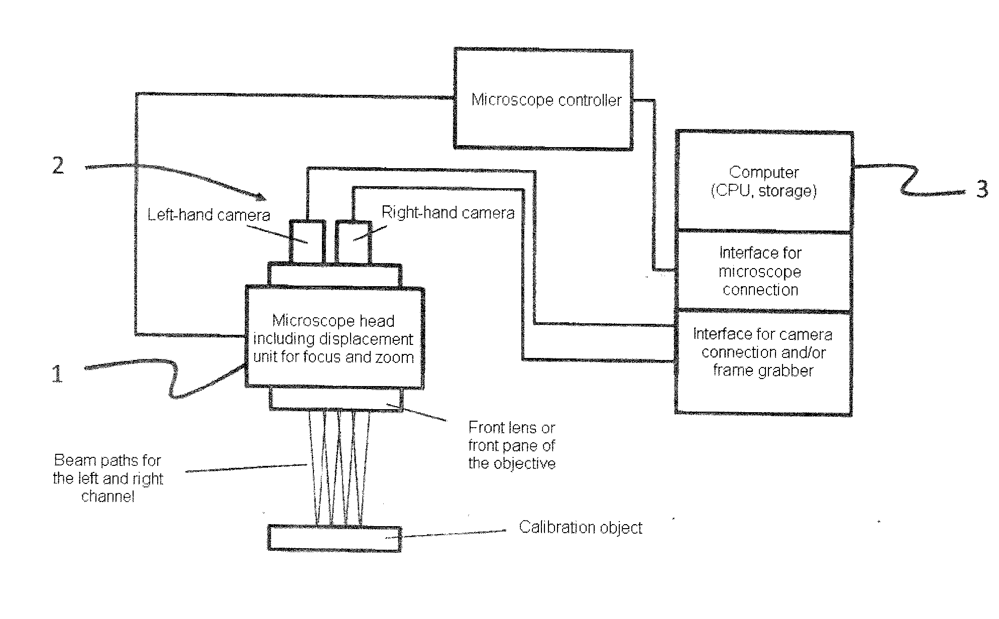
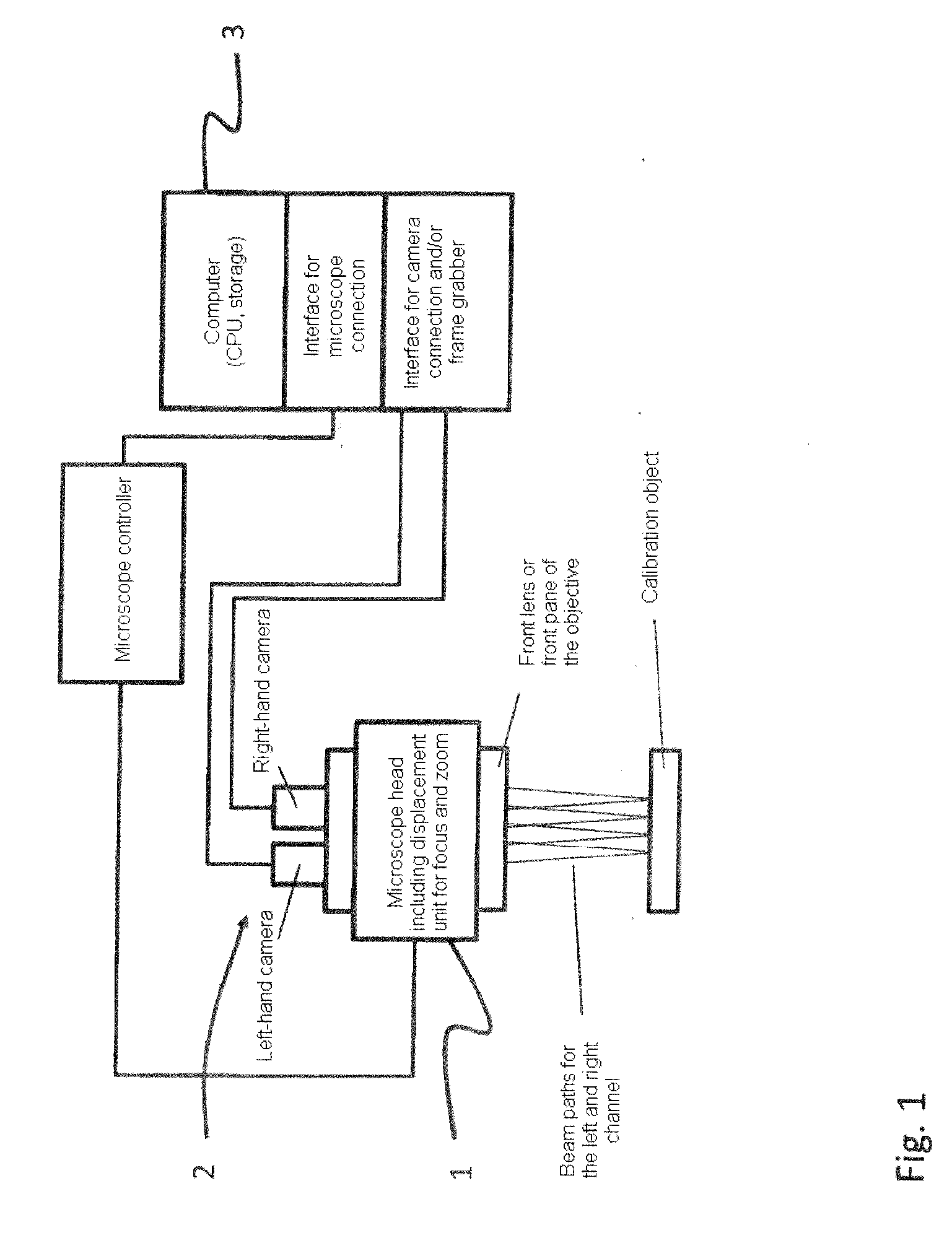
[0016]FIG. 1 depicts a surgical microscope system with a stereo surgical microscope 1 and a stereo camera system 2. The surgical microscope system includes a computer 3 with a data link to the surgical microscope, for example in the form of a frame grabber or a direct wired connection, or by way of a computer interface such as GigE or USB.

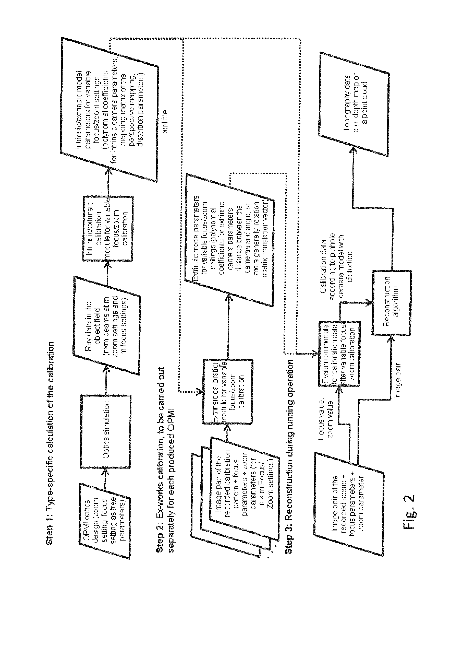
[0017]FIG. 2 depicts a flowchart of a first embodiment for a method according to the invention. In the method, data from the optics simulation, settings of the surgical microscope and real image recordings using the surgical microscope to be calibrated are combined into one workflow, in which the optics simulation forms the basis for the intrinsic calibration, that is, the determination of the camera parameters for the pinhole camera model and the parameters of the distortion mapping, in order thus to increase the accuracy and robustness of a beam reconstruction.

[0018]To this end, focus and zoom positions of the surgical microscope are established ...


PUM


Abstract

The invention relates to a method for the image-based calibration of multi-camera systems with adjustable focus and / or zoom, including the following method steps: calculating a number of beams from an optics simulation for different focus and / or zoom settings or combinations of focus and zoom settings; reading out the focus and / or zoom settings and storing these values with the beams such that a unique assignment is ensured; parameterizing a continuous pinhole camera model for extrinsic and intrinsic calibration of different zoom and / or focus settings of the multi-camera system on the basis of the data from the optics simulation.

Description

CROSS REFERENCE TO RELATED APPLICATION[0001]This application claims priority of German patent application no. 10 2014 210 099.2, filed May 27, 2014, the entire content of which is incorporated herein by reference.FIELD OF THE INVENTION[0002]The invention relates to a method for the image-based calibration of multi-camera systems, in particular surgical microscopes with multi-camera systems, with changeable setting parameters such as focus and zoom. The goal of such a calibration lies in modeling the imaging system so as to be able to use this for a 3D reconstruction of surfaces via stereoscopic methods. Here, geometric modeling of the beam paths of the multi-camera system is paramount since these are mandatory for the 3D reconstruction.BACKGROUND OF THE INVENTION[0003]A method for calibrating multi-camera systems is known, for example, from the publication “Modeling and calibration of automated zoom lenses”, PhD thesis, R. G. Wilson, The Robotics Institute, Carnegie Mellon Universit...

Claims


Application Information

Patent Timeline
Patent Type & Authority Applications(United States)
IPC IPC(8): G02B21/00H04N17/00H04N5/232H04N7/18H04N13/239
CPCG02B21/008H04N7/181H04N5/23296H04N5/23212H04N17/002G02B21/22G02B21/36G06T2207/10056G06T7/85H04N13/246H04N13/239H04N23/675H04N23/69
Inventor SCHWARZ, OLIVERSAUR, STEFANWILZBACH, MARCOLAMOUSKI, DZIANISBERBERICH, MATTHIAS
Owner CARL ZEISS MEDITEC AG
Why Eureka
Try Eureka