Connector system impedance matching

a technology of connecting system and impedance matching, which is applied in the direction of coupling device details, coupling device connection, electric discharge lamp, etc., can solve the problems of increasing the impedance of the signal path at that point, the impedance of the signal path may have various errors or fluctuations along its length, and the impedance of the signal path may vary along the signal path. , to achieve the effect of increasing the impedance, increasing the impedance, and decreasing the impedan

Active Publication Date: 2015-12-03
APPLE INC
View PDF13 Cites 14 Cited by
  • Summary
  • Abstract
  • Description
  • Claims
  • Application Information

AI Technical Summary

Benefits of technology

[0010]These signal path impedances may have various errors or fluctuations along their lengths. For example, a contact in the connector insert may be located above or below a ground plane, where the ground plane is located along a center line of the connector insert. The contact may have a capacitance to the ground plane, where the capacitance increases with the proximity of the contact to the ground plane. Since impedance is inversely proportional to the square root of the capacitance, when the contact is closer to the ground plane, the impedance may decrease. Keeping the spacing between the contact and ground plane relatively constant may allow the impedance to be well controlled along the contact's length, but there may be a discontinuity where the insert contacts extend beyond the ground plane and housing. The nearest ground or fixed potential may be further away at this point, leading to an increase in impedance in the signal path at that point. Conversely, the size of receptacle contacts needed to provide a wiping function and to reliable engage the insert contacts may lead to an increase in capacitance and a resulting decrease in impedance at that point. Also, excess portions of the connector insert and receptacle contacts may create stubs, which may act as capacitors, thereby further reducing the impedance at the connector receptacle contact.
[0011]Illustrative embodiments of the present invention may reduce or at least partially compensate for these and other impedance errors. In one example, the ground plane in the connector insert may extend such that it engages or contacts a corresponding ground plane in a connector receptacle. In this way, the connector insert contacts do not extend beyond this combined ground plane and the discontinuity that would otherwise result may be avoided.
[0012]In these and other embodiments of the present invention, the decrease in impedance near the connector receptacle surface contacts may be reduced. For example, signal contacts having a reduced depth may be provided. These reduced depth contacts may have an increased distance to a center ground plane in the tongue. The increased distance may reduce coupling capacitance, thereby increasing local impedance. In this and other embodiments, power contacts may be deeper or thicker to provide an increase in current handling capability.
[0013]In other illustrative embodiments of the present invention, the ground plane may be thinned below the signal contacts to further increase a distance between a signal contact and the ground plane. In still other illustrative embodiments of the present invention, the ground plane may have openings below the signal contacts. While this may allow cross-talk between signal contacts on a top and bottom of the connector receptacle tongue, the impedance error may be reduced enough to provide an overall improvement in performance. In these and other embodiments, the traces may be offset from each other to reduce this crosstalk.
[0014]In this and other embodiments of the present invention, a ground plane may reside near a center of the tongue. In other embodiments of the present invention, the central plane may be a power plane. Other planes may be located above or below these central planes. Again, these may be power or ground planes. For example, a power plane may be centrally located and ground planes may be positioned above and below the central plane. A high capacitance dielectric may be placed between the power and ground planes in order to form bypass capacitors between power and ground. This capacitance may help to reduce the return path impedance and may help to reduce power supply noise. For example, a dielectric having a dielectric constant or relative permittivity on the order of 100 to 1,000 or higher may be used.
[0015]In the above embodiments of the present invention, impedance errors may be reduced. In these and other embodiments of the present invention, the above impedance errors may be compensated for. For example, traces connected to contacts on the connector receptacle tongue may be arranged to provide higher or lower impedances than the desired impedance of the signal paths in order to compensate for the above, and other, impedance errors. In an illustrative embodiment of the present invention, a distance between these traces and a ground plane may be varied, for example from tens of microns to hundreds of microns, in order to adjust the impedance of a portion of a trace in a tongue. This impedance may be set such that the average or effective impedance for the overall signal trace meets a desired specification or target.

Problems solved by technology

Constraints on physical dimensions of the connector insert and connector receptacle contacts may result in variations in impedance along the signal paths.
These signal path impedances may have various errors or fluctuations along their lengths.
The nearest ground or fixed potential may be further away at this point, leading to an increase in impedance in the signal path at that point.
Conversely, the size of receptacle contacts needed to provide a wiping function and to reliable engage the insert contacts may lead to an increase in capacitance and a resulting decrease in impedance at that point.

Method used


Image

  • Connector system impedance matching
  • Connector system impedance matching
  • Connector system impedance matching

Examples


Embodiment Construction

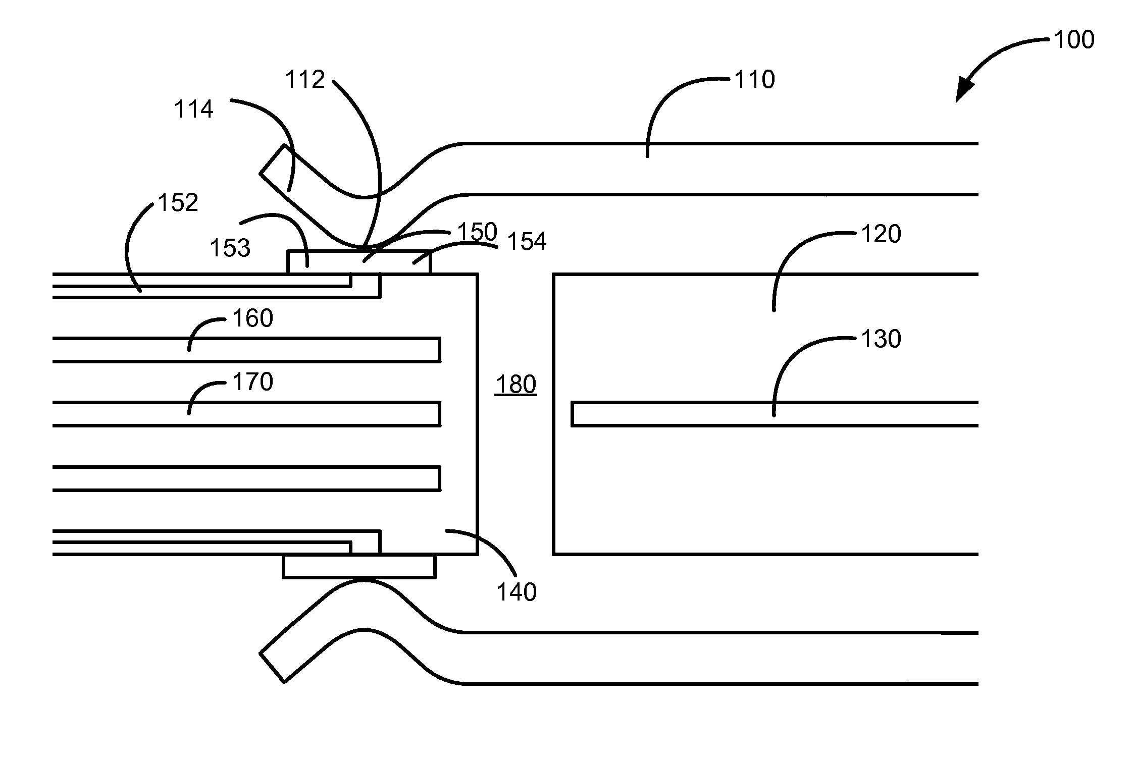
[0050]FIG. 1 illustrates a connector system according to an embodiment of the present invention. This figure, as with the other included figures, is shown for illustrative purposes and does not limit either the possible embodiments of the present invention or the claims.

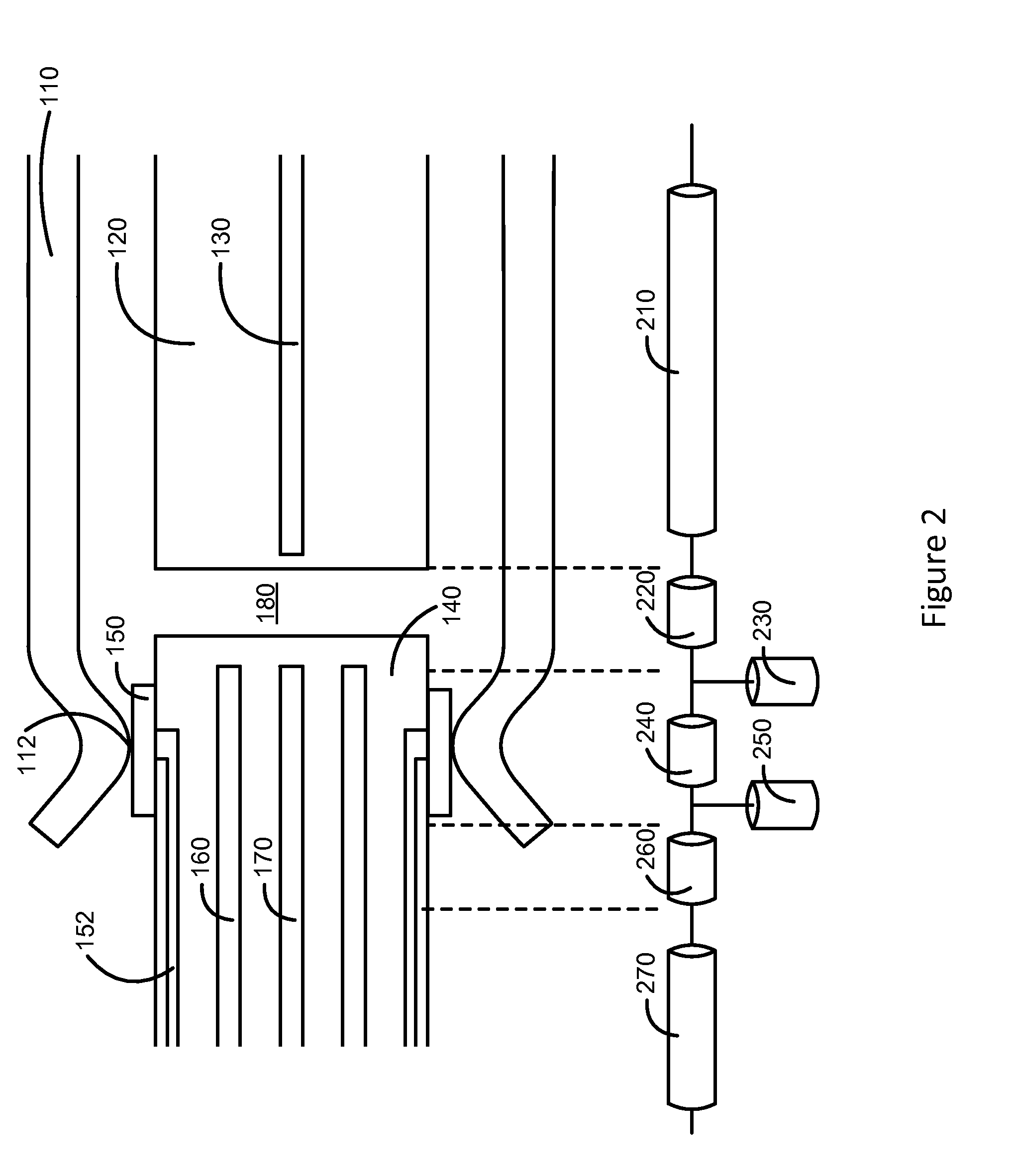
[0051]In this figure, a portion of a connector insert has been inserted into a connector receptacle. Shown are connector insert contacts 110 supported by connector insert housing 120. Connector insert contacts 110 may electrically connect to conductors in a cable (not shown.) A central ground plane 130 may be located in connector insert housing 120 and may be connected to the cable as well. The connector insert may be inserted into a connector receptacle including tongue 140. Tongue 140 may support a number of contacts 150. Traces 152 may electrically connect contacts 150 to circuitry inside a device housing tongue 140. Tongue 140 may further include one or more planes 160 and 170. Planes 160 and 170 may be power sup...


PUM


Abstract

Connector inserts and receptacles that provide signal paths having desired impedance characteristics. One example may provide a connector system having a connector insert and a connector receptacle. Contacts in the connector insert may form signal paths with corresponding contacts in the connector receptacle. Additional traces in the connector insert and receptacle may be part of these signal paths. The signal paths may have a target or a desired impedance along their lengths such that the power paths electrically appear as transmission lines. Constraints on physical dimensions of the connector insert and connector receptacle contacts may result in variations in impedance along the signal paths. Accordingly, embodiments of the present invention may provide structures to reduce these variations, to compensate for these variations, or a combination thereof.

Description

CROSS REFERENCE TO RELATED APPLICATIONS[0001]The present application claims the benefit of U.S. provisional application Nos. 61 / 990,700, filed May 8, 2014, and 62 / 004,834, filed May 29, 2014, which are incorporated by reference.BACKGROUND[0002]The amount of data transferred between electronic devices has grown tremendously the last several years. Large amounts of audio, streaming video, text, and other types of information content are now regularly transferred among desktop and portable computers, media devices, handheld media devices, displays, storage devices, and other types of electronic devices.[0003]Data may be conveyed over cables that may include wire conductors, fiber optic cables, or some combination of these or other conductors. Cable assemblies may include a connector insert at each end of a cable, though other cable assemblies may be connected or tethered to an electronic device in a dedicated manner. The connector inserts may be inserted into receptacles in the communi...

Claims


Application Information

Patent Timeline
Patent Type & Authority Applications(United States)
IPC IPC(8): H01R13/6473H01R13/66
CPCH01R13/665H01R13/6473H01R13/6469H01R12/721
Inventor CORNELIUS, WILLIAMAMINI, MAHMOUD R.GAO, ZHENG
Owner APPLE INC
Why Eureka
Try Eureka