
Machine and a System for Automatically Controlling Noise Reduction Feature of a Communication Device

a communication device and automatic control technology, applied in the field ofsignal processing, can solve the problems of not always using communication devices in noisy environments, background noise is a major problem, and the environment may be extremely noisy, so as to achieve the effect of preserving voice quality, increasing channel capacity, and reducing nois

Inactive Publication Date: 2015-12-03
KONCHITSKY ALON
View PDF2 Cites 0 Cited by
  • Summary
  • Abstract
  • Description
  • Claims
  • Application Information

AI Technical Summary

Benefits of technology

The patent provides a technology that allows users to disable noise reduction in situations where there is no background noise or when it is not needed. This saves processing time, data space, and program space and increases the capacity of communication channels. Additionally, users can adjust the threshold to bypass noise cancellation and preserve voice quality. The technology can be added to existing devices without interfering with their native noise reduction algorithms, improving battery life and reducing power consumption.

Problems solved by technology

Background noise is a major problem when processing audio signals.
However, communication devices are not always used in noisy environments.
Some of these environments may be extremely noisy (bars, crowded restaurants etc.) and some may be extremely quite (home, relaxing lounge etc.).
The noise reduction algorithms, however, come at an expense of battery life, power, MIPS (Millions of Instructions per Second), huge program space, data space and crucial processing time.
Not all communication devices operate in noisy environments.

Method used


Image

  • Machine and a System for Automatically Controlling Noise Reduction Feature of a Communication Device
  • Machine and a System for Automatically Controlling Noise Reduction Feature of a Communication Device
  • Machine and a System for Automatically Controlling Noise Reduction Feature of a Communication Device

Examples


Embodiment Construction

[0035]The following detailed description is directed to certain specific embodiments of the invention. However, the invention can be embodied in a multitude of different ways as defined and covered by the claims and their equivalents. In this description, reference is made to the drawings wherein like parts are designated with like numerals throughout.

[0036]Unless otherwise noted in this specification or in the claims, all of the terms used in the specification and the claims will have the meanings normally ascribed to these terms by workers in the art.

[0037]Hereinafter, preferred embodiments of the invention will be described in detail in reference to the accompanying drawings. It should be understood that like reference numbers are used to indicate like elements even in different drawings. Detailed descriptions of known functions and configurations that may unnecessarily obscure the aspect of the invention have been omitted.

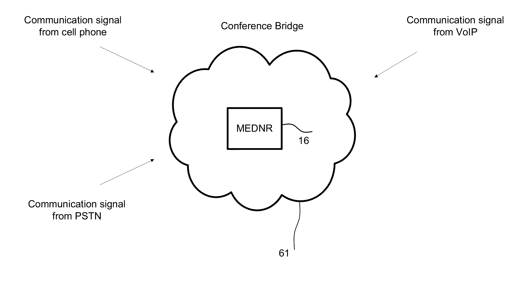
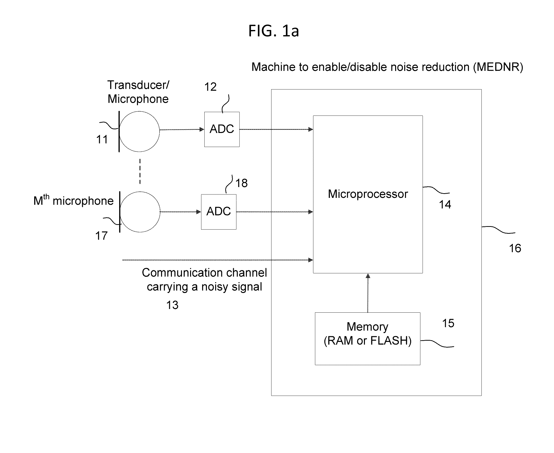
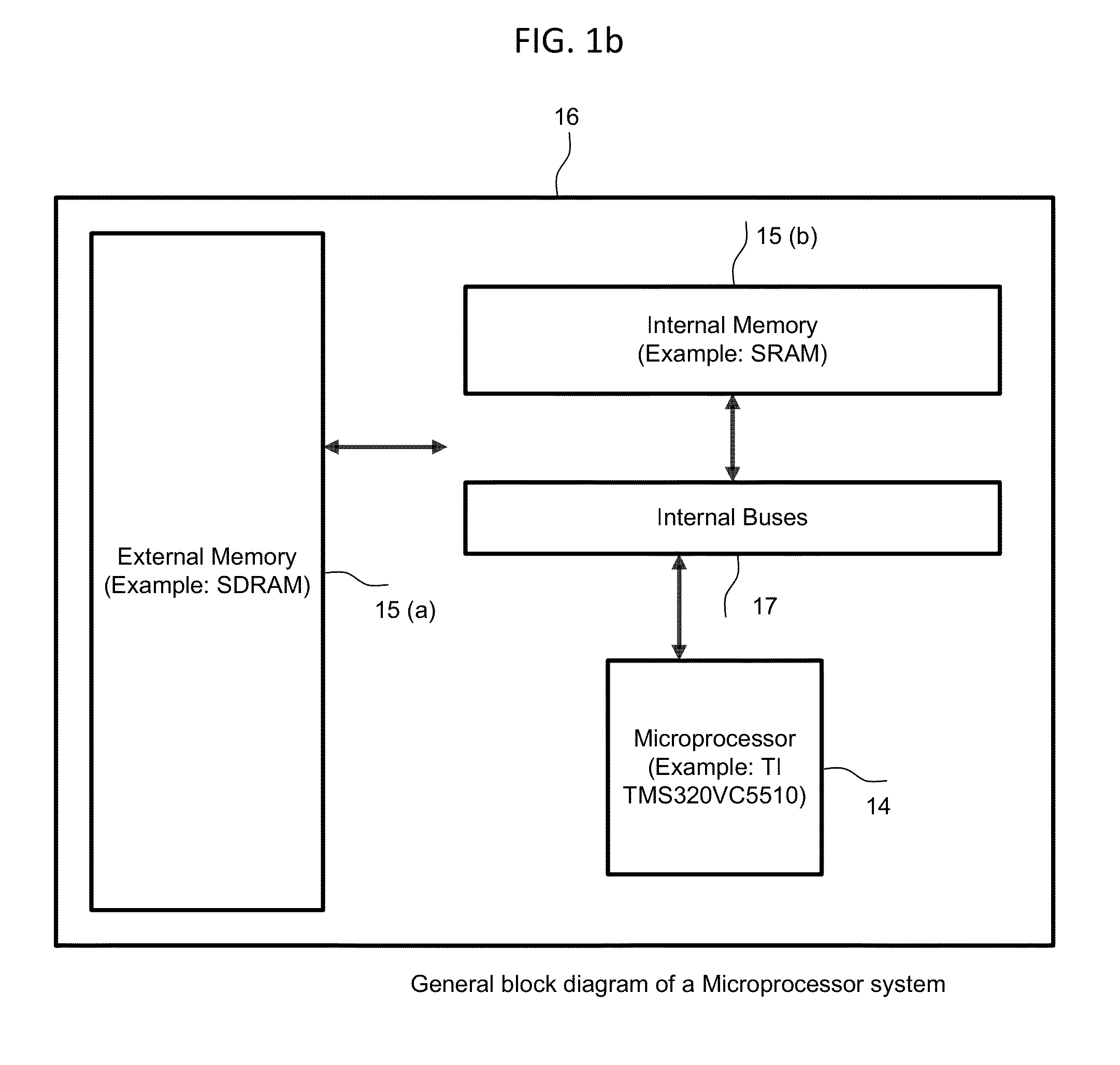
[0038]FIG. 1a shows the embodiments of the Machine for En...


PUM


Abstract

A machine and a system for automatically controlling noise reduction feature of a communication device are disclosed. In one embodiment herein, a receiving module is configured to receive audio signals from the communication device, and a user input. The audio signals are processed by a microprocessor based on the user inputs and a predefined time interval. A comparator is provided for comparing the user input and the processed audio signals, to determine if the processed audio signal is greater or lesser than the user input and the noise reduction feature of the communication device is correspondingly enabled or disabled.

Description

CROSS-REFERENCE TO RELATED APPLICATIONS[0001]This application is a continuation in part to U.S. patent application Ser. No. 14 / 289,137 filed on or about May 28, 2014 which is a continuation in part of U.S. patent application Ser. No. 13 / 083,513 (now U.S. Pat. No. 8,775,172) filed on Apr. 8, 2011 which claims the benefit of provisional patent application 61 / 389,203 filed on Oct. 2, 2010. The contents of the related patent applications are incorporated herein by reference as if restated herein. This application claims the priority dates of the related patent applications.FIELD OF THE INVENTION[0002]The present invention relates to the field of signal processing and providing clear, high quality voice both in presence and absence of background noise in voice communication systems, devices, telephones, voice communication gateways, multi-channel environments and other communication environments.[0003]This invention is in the field of processing audio signals in cell phones, Bluetooth he...

Claims


Application Information

Patent Timeline
Patent Type & Authority Applications(United States)
IPC IPC(8): H04R3/00
CPCH04R3/00H04R1/1083H04R2460/03G10L21/0208G10L2025/783G10L2021/02166
Inventor KONCHITSKY, ALON
Owner KONCHITSKY ALON
Learn More