Method for forming a pressed component, method for manufacturing a pressed component, and die apparatus for forming a pressed component

a technology of pressed components and dies, which is applied in the direction of mechanical equipment, brake types, etc., can solve the problems of unnecessary forming of tapered surfaces, die equipment including such dies, etc., and achieve the effect of reducing the thickness, forming accurately, and reducing the for

Inactive Publication Date: 2015-12-10
FCC KK
View PDF5 Cites 15 Cited by
  • Summary
  • Abstract
  • Description
  • Claims
  • Application Information

AI Technical Summary

Benefits of technology

[0008]According to the feature of the method for forming a pressed component according to the present invention, a preform having a tubular portion and a sloping portion extending from one end of the tubular portion is used. A portion of the sloping portion is cut off, and the remaining portion is bent toward the piercing die within the forming space and is then compressed so as to form the corner portion. Namely, in the method for forming a pressed component according to the present invention, instead of pressing and crushing a portion (the sloping portion) of the preform which becomes the corner portion such that that portion (the sloping portion) plastically deforms while buckling, the remaining portion is pressed in a direction intersecting the direction in which the sloping portion extends so as to bend the remaining portion. Therefore, it is possible to form the corner portion while increasing its thickness with a smaller force compared with the conventional technique. As a result, the forming die apparatus and die equipment including the forming die apparatus can be made small and simple.
[0009]When the method for forming a pressed component according to the present invention is employed, it is unnecessary to form a tapered surface on the peripheral edge of a blank as in the case of the above-described conventional technique. Therefore, a die for forming a tapered surface, die equipment including such a die, and a step of forming a tapered surface become unnecessary. Also, in the method for forming a pressed component according to the present invention, a portion (a sloping portion) of the preform which becomes the corner portion is pressed while being bent. Therefore, the corner portion can be accurately formed without causing folding of the material. The cup-like shape of the pressed component refers to the shape of a tubular member which is bent inward at at least one end thereof so as to form a bottom and which has a circular or non-circular through hole formed in the bottom.
[0011]According to the second feature of the method for forming a pressed component according to the present invention, the sloping portion of the preform extends from the tubular portion while bending smoothly in a curved shape. This avoids the occurrence of a portion in which stress concentrates when the corner portion is formed. Thus, it becomes possible to form the corner portion by plastically deforming the sloping portion while effectively preventing folding or curling of the sloping portion. Also, since the sloping portion of the preform is formed in a curved shape, it is possible to prevent a decrease in the thickness (so-called thinning) of the sloping portion during formation of the sloping portion. As a result, it is possible to effectively prevent thinning of the corner portion of the pressed component. The greater the radius of curvature of the sloping portion of the preform, the greater the degree to which thinning of the corner portion of the pressed component can be prevented.
[0013]According to the third feature of the method for forming a pressed component according to the present invention, the tubular portion of the preform is tapered such that its diameter decreases toward the sloping portion. Therefore, the inner fixing and supporting portion of the piercing die and the outer fixing and supporting portion of the holding body which fixedly support the preform can have a tapered shape corresponding to the tapered shape of the tubular portion. Thus, an operation of causing the piercing die and the holding body to approach each other and separate from each other can be realized by displacement along a single axis. As a result, the preform can be supported easily and accurately, and the size and the degree of complexity of equipment can be decreased.

Problems solved by technology

Therefore, a die for forming a tapered surface, die equipment including such a die, and a step of forming a tapered surface become unnecessary.

Method used


Image

  • Method for forming a pressed component, method for manufacturing a pressed component, and die apparatus for forming a pressed component
  • Method for forming a pressed component, method for manufacturing a pressed component, and die apparatus for forming a pressed component
  • Method for forming a pressed component, method for manufacturing a pressed component, and die apparatus for forming a pressed component

Examples


Embodiment Construction

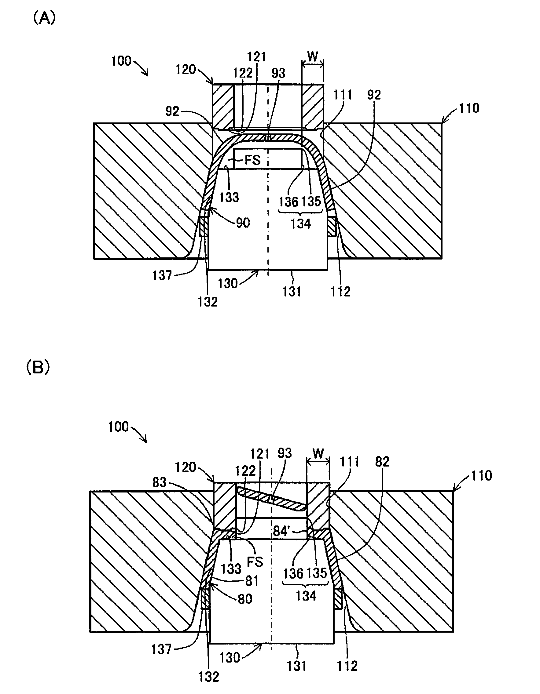
[0025]One embodiment of a pressed component-forming method according to the present invention will be described below with reference to the drawings. FIG. 1 is a cross-sectional view schematically showing the structure of a pressed component 80 formed by the pressed component-forming method according to the present invention. The figures referred to in the description are schematically illustrated with some components exaggerated in order to facilitate an understanding of the present invention. Therefore, components shown in the drawings may have dimensions, proportions, etc. which are different from the actual ones.

[0026]First, the pressed component 80 formed by the pressed component-forming method according to the present invention will be briefly described. The pressed component 80 is a component which is used as a clutch guide, an end plate, a clutch piston, or a cup for a plate carrier of a clutch mounted on a vehicle such as an automobile or a motorcycle. The pressed component...


PUM

PropertyMeasurementUnit
shapeaaaaaaaaaa
bendingaaaaaaaaaa
diameteraaaaaaaaaa

Abstract

The present invention provides a method for forming a pressed component, a method for manufacturing a pressed component, and a die apparatus for forming a pressed component which can reduce the load necessary for forming to thereby decrease the size and the degree of complexity of equipment used for forming a pressed component. A pressed component (90) is formed by pressing a preform (90) having a tapered tubular portion (91) and a sloping portion (92) which is provided at an end of the tubular portion and curved in a circular arc. The pressing is performed by a forming die apparatus (100) including a holding body (110), a piercing punch (120), and a piercing die (130). In a state in which the tubular portion (91) of the preform (90) is held by an outer fixing and supporting portion (112) of the holding body (110) and an inner fixing and supporting portion (132) of the piercing die (130), the forming die apparatus (100) cuts off a portion of the sloping portion (92) using an outer cutting edge (122) of the piercing punch (120) and an inner cutting edge (135) of the piercing die (130) and then causes a pressing portion (121) of the piercing punch (120) to bend and press the remaining portion of the sloping portion (92) within a forming space (FS) to thereby form a corner portion (83).

Description

TECHNICAL FIELD [0001]The present invention relates to a method for forming a pressed metal component including a tubular member having one end portion bent inward to have a cup-like shape, a method for manufacturing such a pressed component, and a die apparatus for forming such a pressed component.BACKGROUND ART [0002]In general, cup-shaped pressed metal components having a roughly U-shaped cross section, such as a clutch guide, an end plate, a clutch piston, or a cup for a plate carrier, are used in a power transmission apparatus mounted on an automobile, a motorcycle, or the like. These pressed components are typically formed by drawing, stretch flanging, upsetting, blanking, and cutting.[0003]For example, below-described Patent Document 1 discloses a method for forming a pressed component in which after a plate-shaped blank is formed into a cup-shaped intermediate product by deep drawing, an edge portion of the cup-shaped intermediate product is upset through compression thereof...

Claims


Application Information

Patent Timeline
Patent Type & Authority Applications(United States)
IPC IPC(8): B21D28/28
CPCB21D28/28B21D53/34B21D35/001B21D22/00
Inventor SHIMIZU, YUKITOUDA, YUTAKA
Owner FCC KK
Why Eureka
Try Eureka