Hole-Saw

a hole-saw and cutting tool technology, applied in the field of hole-saws, can solve the problems of wasting raw materials, wobbling between the parts of the type of hole-saw, etc., and achieve the effects of saving raw materials, saving raw materials, and being more economical to produ

Inactive Publication Date: 2015-12-10
SPERA THOMAS J
View PDF15 Cites 4 Cited by
  • Summary
  • Abstract
  • Description
  • Claims
  • Application Information

AI Technical Summary

Benefits of technology

[0024]One or more embodiments herein thereby include a hole-saw that substantially eliminates (e.g., by about 99%) the wobbling that is common with other hole-saws on the market, yielding a faster, cleaner and more precise cut. Alternatively or additionally, embodiments herein include a hole-saw that uses a double-edged cutter, yielding twice the cut from each saw. A hole-saw according to at least some embodiments only uses about 30% of the metal to produce (compared to existing hole-saws), meaning that it is more economical to produce and saves a lot of raw materials. As yet another additional or alternative feature, the pilot bit is secured to the mandrel using a locking collet, making the pilot bit easier to replace and making the hole-saw able to use standard drill bits. These changes, especially when combined, make the tool more accurate, faster, and safer to use, all at a fraction of the cost of the standard hole-saws.
[0025]According to some embodiments, a hole-saw herein advantageously avoids cutting your hand if you were to try to slow down the drill with your hand. As compared to existing hole-saws, the mandrel according to one or more embodiments is simpler and less expensive to produce. Additionally or alternatively, the hole-saw herein uses less metal to produce, meaning that it costs less to manufacture. In at least some embodiments, the mandrel herein avoids other problems that plague existing hole-saws, including the problem that a mandrel has heretofore only been good for a certain range of sizes until you need the next size mandrel (costing more to purchase).

Problems solved by technology

This type of hole-saw suffers from wobbling between the parts.
Moreover, it is only designed as a single edged cutter; when it gets dull, it is thrown away.

Method used


Image

  • Hole-Saw
  • Hole-Saw
  • Hole-Saw

Examples


Embodiment Construction

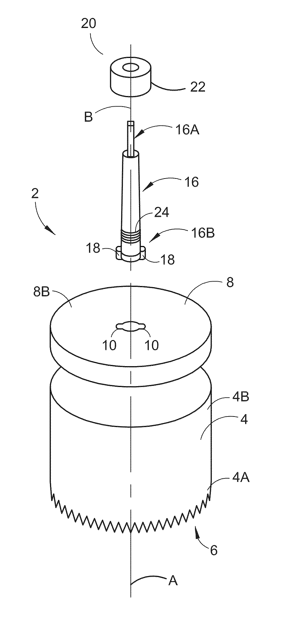
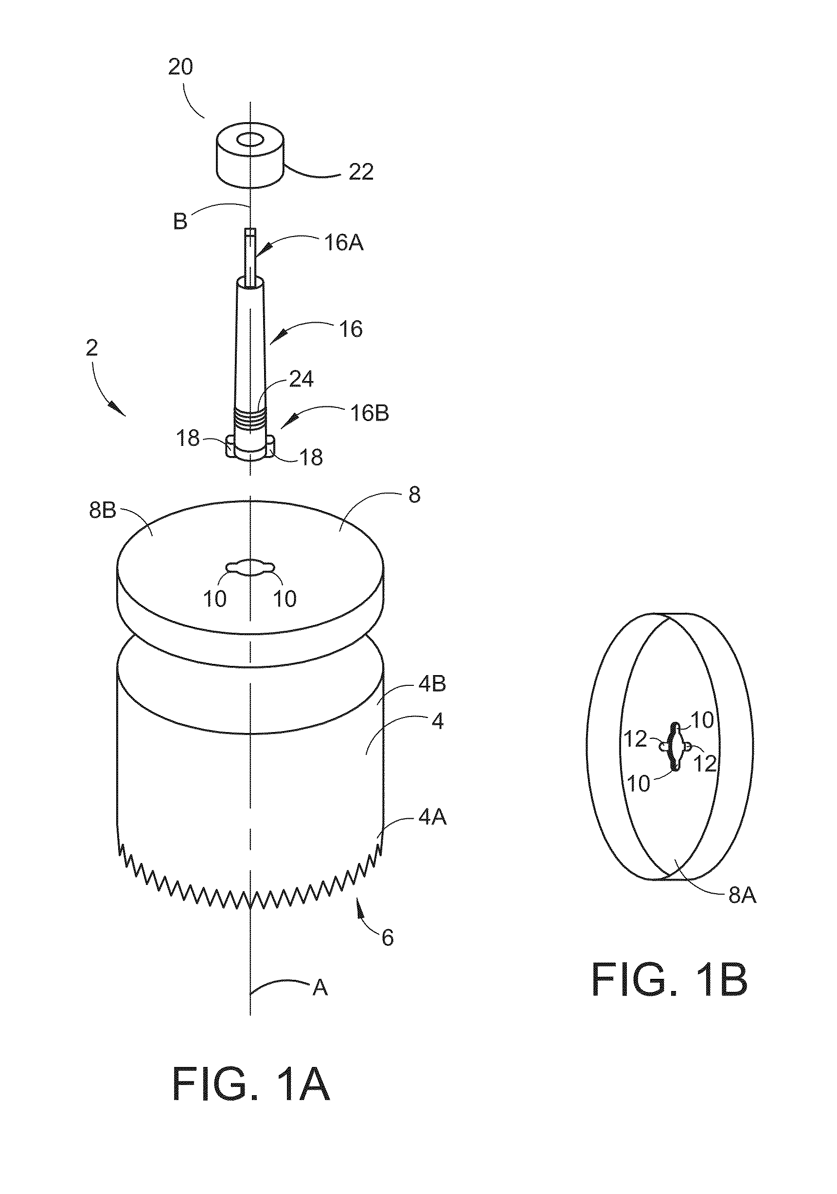
[0042]FIGS. 1A-1B illustrate a hole-saw 2 according to one or more embodiments. The hole-saw 2 includes a cylindrical body 4, a plate 8, and a mandrel 16.

[0043]The body 4 has a first cutting edge 6 formed at a first end 4A of the body 4 that is open. This first cutting edge 6 is disposed about a rotational axis A of the body.

[0044]The plate 8 is disposed at a second end 4B of the body 4 different than the first end 4A. Although illustrated as separate from the body 4 in FIGS. 1A-1B for explanatory purposes, the plate 8 is rotationally coupled to the body 4 such that rotation of the plate 8 or the body 4 results in rotation of the other. The plate 4 is oriented perpendicular to the body's rotational axis A, as shown.

[0045]Notably, the plate 8 has lateral slots 10 formed through the plate 8. As shown in FIGS. 1A-1B, for example, the plate 8 has a single pair of lateral slots 10 that extend laterally, e.g., in opposite directions, from a circular hole through the plate's center. The pl...


PUM

PropertyMeasurementUnit
circumferenceaaaaaaaaaa
lengthaaaaaaaaaa
outer circumferenceaaaaaaaaaa

Abstract

A hole-saw comprises a cylindrical body, a plate, a mandrel, and a clamping member. A cutting edge is formed at an open end of the body and is disposed about the body's rotational axis. The plate is disposed at an opposite end of the body, is rotationally coupled to the body, and is oriented perpendicular to the body's rotational axis. The plate has lateral slots formed through the plate and lateral grooves formed in the plate's distal surface in an orientation transverse to the slots. The mandrel's proximal section forms an arbor shaft, and its distal section includes lateral bosses sized to insert through the plate's slots and rest in the plate's grooves. The clamping member has a body that is movable along the mandrel's longitudinal axis to engage the plate's proximal surface and clamp the plate between the clamping member and the bosses resting in the plate's grooves.

Description

RELATED APPLICATIONS[0001]This application claims priority from U.S. Provisional Patent App. No. 62 / 010,278 filed 10 Jun. 2014, which is incorporated herein by reference in its entirety.BACKGROUND[0002]The most common type of hole-saw on the market today is made up of two components, the mandrel and the hole-saw cup. The mandrel has a threaded portion onto which the hole-saw cup is screwed to, and then is locked in place with two sliding pins. These pins are attached to the mandrel and slip into two receiving holes on the upper surface of the hole-saw cup. This type of hole-saw suffers from wobbling between the parts. Moreover, it is only designed as a single edged cutter; when it gets dull, it is thrown away.SUMMARY[0003]A hole-saw according to one or more embodiments herein comprises a cylindrical body, a plate, a mandrel, and a clamping member.[0004]The body has a first cutting edge formed at a first end of the body that is open. The first cutting edge is disposed about a rotatio...

Claims


Application Information

Patent Timeline
Patent Type & Authority Applications(United States)
IPC IPC(8): B23B51/04
CPCB23B51/0473B23B51/0426B23B2251/247B23B2251/46Y10T408/8967B23B2251/70B23B2260/056Y10T408/895B23B2251/603
Inventor SPERA, THOMAS J.
Owner SPERA THOMAS J
Why Eureka
Try Eureka