Fuel separation method

a technology of fuel separation and fuel, which is applied in the direction of machines/engines, mechanical equipment, and membranes, etc., can solve the problems of low start-up property of ethanol and achieve the effect of wide compositional rang

Inactive Publication Date: 2015-12-10
TOYOTA JIDOSHA KK +2
View PDF1 Cites 14 Cited by
  • Summary
  • Abstract
  • Description
  • Claims
  • Application Information

AI Technical Summary

Benefits of technology

[0025]According to the fuel separation method of the first and second aspects of the invention, it is possible to obtain an auxiliary fuel that is preferable for control of internal combustion engines, from an ethanol-blended gasoline fuel. According to the fuel separation method of the first aspect of the invention, in particular, it is possible to obtain an auxiliary fuel that is preferable for control of internal combustion engines, from ethanol-blended gasoline fuels with a wide compositional range.

Problems solved by technology

Because ethanol has a high boiling point and large latent heat of vaporization, it is difficult to form a combustible gaseous blend at the starting up of the internal combustion engine, and therefore ethanol has the drawback of a low start-up property for the internal combustion engine.

Method used


Image

  • Fuel separation method
  • Fuel separation method
  • Fuel separation method

Examples


example 1

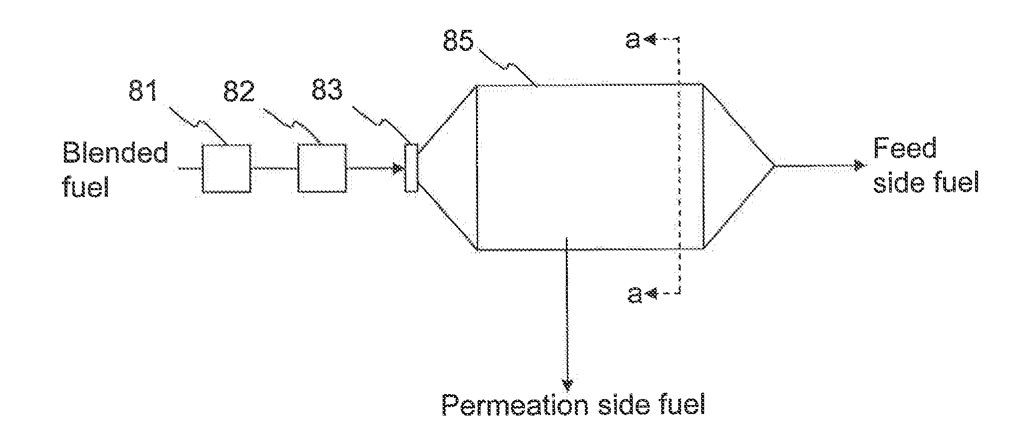
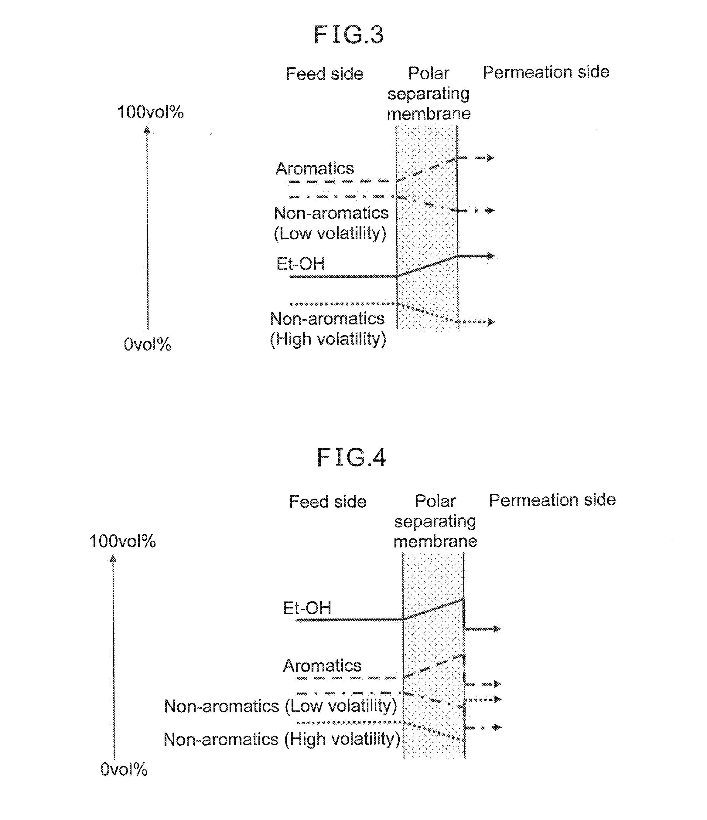
[0086]In this example, the device illustrated in FIG. 8 was used to separate an E10 ethanol-blended gasoline fuel, as a mixture of approximately 10 vol % ethanol and approximately 90 vol % gasoline, at a separation temperature of 148° C. The polar separating membrane member used consisted of a D400-DENO aliphatic epoxy crosslinked polyetheramine on a porous ceramic support, as described in U.S. Provisional Patent Application Ser. No. 61 / 476,988. The evaluation results are shown in Table 1 below.

TABLE 1Results of membrane separation of E10 fuel at 148° C.BeforeAfter membranemembraneseparation (wt %)separationPermeationFeed(wt %)sidesideComponentNon-aromatic17919high-volatilitygasoline componentsNon-aromatic523757low-volatilitygasoline componentsAromatic gasoline212919componentsEthalnol component1045Total Yield (wt %)1002476EvaluationReid vapor pressure (psi)859Octane value (RON*)MediumHighLow(92)(101)(69)(RON*): Research Octane Number

[0087]As clearly seen in Table 1, membrane separat...

example 2

[0088]In this example, the device illustrated in FIG. 8 was used to separate an E70 ethanol-blended gasoline fuel, as a mixture of approximately 70 vol % ethanol and approximately 30 vol % gasoline, at a separation temperature of 85° C. The evaluation results are shown in Table 2 below.

TABLE 2Results of membrane separation of E70 fuel at 85° C.BeforeAfter membranemembraneseparation (wt %)separationPermeationFeed(wt %)sidesideComponentNon-aromatic685high-volatilitygasoline componentsNon-aromatic17920low-volatilitygasoline componentsAromatic gasoline10511componentsEthanol component677864Total Yield (wt %)1002773EvaluationReid vapor pressure (psi)5.67.55.5Octane valueHighHighHigh

[0089]As clearly seen in Table 2, membrane separation at a relatively low temperature of 85° C. in Example 2 made it possible to increase the proportion of non-aromatic high-volatile gasoline components, and thereby increase the Reid vapor pressure value, in the blended gasoline fuel obtained at the permeation ...


PUM

PropertyMeasurementUnit
temperatureaaaaaaaaaa
pressureaaaaaaaaaa
temperatureaaaaaaaaaa

Abstract

A fuel separation method by which auxiliary fuel is separated from blended gasoline fuel for a flexible fuel vehicle capable of using ethanol-blended gasoline fuel, the method including the following steps (a) and (b): (a) a step in which, when the ethanol concentration is low, the blended gasoline fuel is separated by a polar separating membrane member at a relatively high separation temperature to obtain, at the permeation side of the membrane, a first auxiliary fuel enriched with the aromatic gasoline components and ethanol component, and (b) a step in which, when the ethanol concentration is high, the blended gasoline fuel is separated by a polar separating membrane member at a relatively low second separation temperature to obtain, at the permeation side of the membrane, a second auxiliary fuel enriched with the non-aromatic high-volatile gasoline components.

Description

TECHNICAL FIELD[0001]The present invention relates to a fuel separation method for a flexible fuel vehicle, and particularly to a fuel separation method whereby auxiliary fuel is separated from an ethanol-blended gasoline fuel.BACKGROUND ART[0002]In recent years, internal combustion engines have become known that use multiple types of fuel. Vehicles in which such internal combustion engines are mounted are known as flexible fuel vehicles (FFV), and known examples include vehicles that can use gasoline and ethanol, either alone or as blends.[0003]As blended fuels of gasoline and ethanol, there are used ethanol-blended gasoline fuels with a wide range of compositions, from E3 (blend of approximately 3% ethanol with approximately 97% gasoline, by volume ratio) to E85 (blend of approximately 85% ethanol with approximately 15% gasoline, by volume ratio). Internal combustion engines for flexible fuel vehicles must carry out combustion optimized for such a wide range of compositions.[0004]...

Claims


Application Information

Patent Timeline
Patent Type & Authority Applications(United States)
IPC IPC(8): C10L1/18B01D61/00
CPCC10L1/18B01D61/00C10L2290/548C10L2270/023C10L1/1824B01D61/362F02D19/0655F02D19/0671B01D2311/08B01D2311/25Y02T10/30B01D2311/04
Inventor IWASHITA, YOSHIHIROUEDA, TAKANORIPARTRIDGE, RANDALL D.LUCCHESI, ROBERTJOHNSON, PAUL O.KELLOGG, GEORGE L.
Owner TOYOTA JIDOSHA KK
Why Eureka
Try Eureka